Arduino Nano Pinout, Projects & Spec

Arduino Nano Pinout

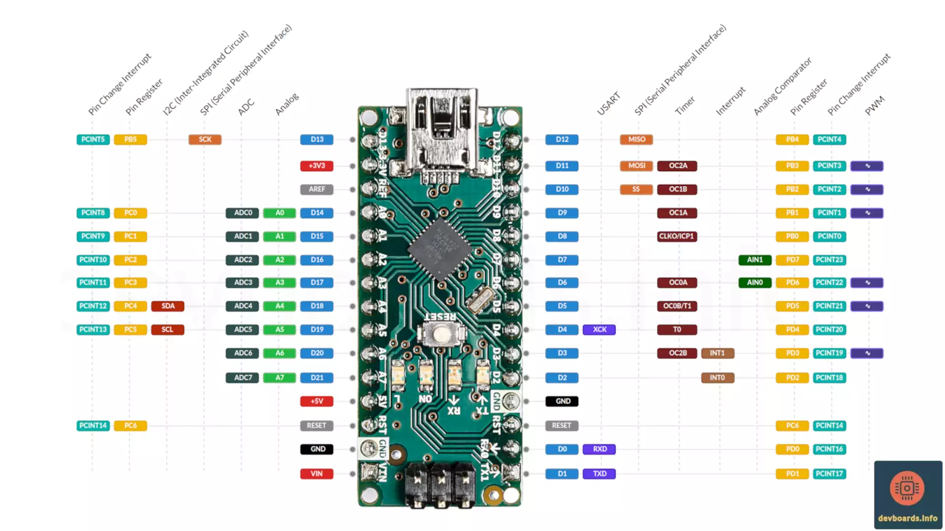
The Arduino Nano is a compact and powerful development board designed for hobbyists, students, and professionals alike. Based on the ATmega328 microcontroller, this board is a smaller and more affordable version of the popular Arduino Uno Rev3 board. Despite its smaller size, the Arduino Nano packs a punch with its powerful features and wide range of capabilities featuring:

  • Wide range of input and output pins, including 14 digital I/O pins of which 6 are PWMs
  • 8 analog inputs
  • 32 KB of Flash, 2 KB of SRAM and 1 KB of EEPROM
  • 16 MHz quartz crystal
  • USB Mini B connection for programming and power
  • ICSP header for programming with an external programmer
  • Support for all known communication protocols like UART, SPI and I2C
  • Reset button

The Arduino Nano is a great choice for projects that require a small, portable, and low-cost microcontroller board. It is well-suited for projects such as controlling motors, reading sensors, or controlling LEDs.


Arduino Nano Pin Headers and Components  

In this section we review the board pinout and will have an overview on its physical properties as well as major components on the board.

Dimensions

The board measures 18mm x 45mm.

Arduino Nano Dimensions18 mm45 mm

The ATmega328P Microcontroller

The main processor of the Arduino Nano is the ATmega328P microcontroller in 32-pin quad flat package (VQFN). The letter 'P' in the microcontroller's name is for Picopower, referring to the fact that it has less power consumption than the ATmega328 which is used in Arduino Uno Rev3. Otherwise, their technical specifications are the same.

Arduino Nano's Microcontroller

Digital I/O Pins

D0 to D21

Arduino Nano has 14 digital input/output pins labeled from D2 to D13.

A digital pin can be used either as input or output pin. This should be specified first using the pinMode function as below:

void setup() {
  pinMode(3, INPUT);        // pin 3 will be used as input
  pinMode(5, OUTPUT);       // pin 5 will be used as ouptut
  pinMode(8, INPUT_PULLUP); // pin 8 will be used as input with pullup resistor internally set by the microcontroller
}

When the pin mode is set, you can read the value of an input pin like this:

pin3Value = digitalRead(3); // read current value of the pin 3 previously set as input

Also to write a digital value to a pin, you can call the digitalWrite function passing one of the constant values HIGH or LOW along with the pin number to write it to:

digitalWrite(5, HIGH); // set pin 5 value to 5V

When a pin mode is set to INPUT_PULLUP, the given pin will be internally connected to the 5V so that if the given pin is floated (i.e. you don't connect it to to either of 5V or GND) it will be read as HIGH.

The first two digital pins D0 and D1 are labeled as RX0 and TX1 on Arduino Nano pinout. It's because they're used for serial communication when the board is connected via USB to computer. So it's better not to use them until you really ran out of digital pin for your project.

Also all the analog pins of the board can be used as digital pin. This is explicitly mentioned in the documentation of digitalRead() function. But it's important to note that pins A6 and A7 can only be used as digital output, not digital input.

Arduino Nano Digital Pins

Analog Input Pins

A0 to A7

The board provides 8 analog input pins labeled A0 to A7 connected to its 10-bit ADC. They can be used for reading analog signals such as temperature sensors, light sensors, and potentiometers.

To read an analog value from a pin, the analogRead() function can be used:

int value = analogRead(14); // read the value of pin 14 as a number between 0 to 1023 

Arduino Nano Analog Pins

Reset Button

The reset button can be used to restart the microcontroller or to put it into bootloader mode for uploading new sketches. It has the same effect as connecting the RST pins to the ground.

Arduino Nano Reset Button

ICSP Header

The ICSP header is intended for programming the board with an external programmer. It's another way of programming the board. You can connect a programmer board (a dedicated hardware) to these pins and transfer your firmware to the board via that. You can also use another Arduino board as a programmer. It's mostly used in cases where you can't program the board using USB via Arduino IDE.

Arduino Nano ICSP Headers

USB Port

The board has a USB Mini B port, which can be used for programming the board as well as providing power to the board. Also when the board is connected to the computer, any data transfer via Serial library is done via this connector.

Arduino Nano USB Port

LEDs

The board has 4 builtin LEDs of which 1 is accessible in code:

  • TX LED: Turns on whenever the board is transmitting data via USART through USB connector.
  • RX LED: Turns on whenever the board is receiving data via USART through USB connector.
  • Power LED (Labeled "ON"): Stays on as long as the board is powered (obviously)
  • L LED: It's connected to the D13 pin. It can be toggled on or off by setting that pin to HIGH/LOW correspondingly.

Here is the Blink example code provided by Arduino IDE that turns the on board LED on and off every second. As you can see, the LED_BUILTIN is a constant that contains the pin number that is connected to the built-in LED of the board. In Arduino Nano, the value of LED_BUILTIN is 13.

/* Credit: Arduino.cc blink example */

// the setup function runs once when you press reset or power the board
void setup() {
  // initialize digital pin LED_BUILTIN as an output.
  pinMode(LED_BUILTIN, OUTPUT);
}

// the loop function runs over and over again forever
void loop() {
  digitalWrite(LED_BUILTIN, HIGH);  // turn the LED on (HIGH is the voltage level)
  delay(1000);                      // wait for a second
  digitalWrite(LED_BUILTIN, LOW);   // turn the LED off by making the voltage LOW
  delay(1000);                      // wait for a second
}

Arduino Nano LEDs

USB To Serial Converter Chip

Arduino Nano comes with a USB To Serial converter chip on the back of the board. When sending or receiving data via RX and TX pins, they go to this chip and get converted to the USB protocol and vice versa. This allows your program on the board to communicate with the computer via serial interface and abstract away the USB protocol completely.

Arduino Nano USB to Serial Converter Chip


Powering Arduino Nano  

The GPIO pins of the board require 5V to work and the board itself can be powered in three different way: USB Connection, VIN pin and +5V pin.

USB Connection: The Arduino Nano has a built-in USB Mini B connection, allowing it to be powered and programmed directly from a computer or laptop. This is a convenient and easy option for many projects, especially when working on a desktop or in a laboratory setting.

VIN

The VIN pin can be used to power the board with an external voltage source. This pin is regulated on-board, so it can accept a wide range of voltage levels, from 7-12 V.

Powering Arduino Nano Via VIN Pin

+5V

This pin outputs a regulated 5V voltage. The voltage comes from either VIN pin or the USB. But it can also be used to give the power to the board. When it's used as input, it must be provided with a 5V regulated voltage. When used as voltage output, this pin can be used to power other components or devices in your project, such as sensors or actuators.

Powering Arduino Nano Via 5V Pin

GND

When powering the board via 5V pin or VIN pin, remember to connect the GND pin of the board to your power supply ground. There are two GND pins in Arduino Nano; one on each side.

Arduino Nano GND Pin

+3V3

Arduino Nano provides a 3.3V pin that is an output of the onboard regulator. You can use it to power the sensor or other modules in the project that require lower voltage level.

Arduino Nano 3.3V Pin

Regardless of how you choose to power the Arduino Nano, it is important to ensure that you select a power source that is appropriate for your project and that meets the voltage and current requirements of the board and your connected components.

The I/O pins of the board are capable of providing up to 40 mA of current. Any use-cases that requires more current, should be powered by an external power source.

RESET

Arduino Nano has two reset pins labeled RST that if gets connected to the GND will reset the board. That's exactly what happens when you push the reset button available on the board. The board also contains a small circuit that resets the board when programming a new sketch on it. That's why you don't need to hold the reset button on the board in order to program it.

Arduino Nano Reset Pins

AREF

The AREF pin is used to provide the voltage level that should be used as a reference for ADC module of the processor. The board has a 10 bit ADC which means any analog input voltage will be converted to a number between 0 to 1023. By default the board considers the input voltage (i.e. 5V) as a reference and consider a signal on that level as 1023 and any signal with a value less than 5V will be converted to a number between 0 to 1023 accordingly. When the AREF is provided with a voltage, that voltage will be considered as 1023 and all the voltage level below that will be mapped accordingly.

In order to use it, you should enable it first by calling analogReference(EXTERNAL).

Arduino Nano AREF Pin


Arduino Nano Pinout and Peripherals  

The ATmega328P of the Arduino Nano provides a range of peripherals to utilize in a project. Some of the most important peripherals include:

Arduino Nano PWM Pins

D3 D5 D6 D9 D10 D11

PWM pins are marked as on Arduino Nano pinout as well as the Arduino Nano board itself. By default the PWM frequency is 490 Hz, except for pins D3 and D11 that use 980 Hz by default.

To generate a PWM signal on one of the PWM capable pins, you can use the analogWrite() function:

analogWrite(3, 127); // generates a PWM output on pin 3 with 50% duty cycle

The duty cycle of the PWM signal can be adjusted using the second parameter with a number between 0 to 256.

The PWM signals are being produced using the Timer/Counter peripherals of the processor. So in order to do any customization on the PWM signal, like changing the frequency or duty cycle, one should initialize registers corresponding to the timer producing those PWM signals.

I/O Ports Registers

The ATmega328P has divided I/O pins in three groups (or as it's called in its datasheet: three Ports): Port B, C and D. The pins assigned to each port are:

  • Port B: Digital pin 8 to 13
  • Port C: Analog pins
  • Port D: Digital pin 0 to 7

Each port has three registers for configuring and accessing the I/O pins on that port as well as reading and writing them.

PB0 to PB5

PC0 to PC6

PD0 to PD7

The registers of each port are named as (replace the 'x' with the port name):

DDRx - The Data Direction Register for Port x. It's both readable and writable.

In order to set a pin to input or output you should set the corresponding bit in this register to 1 or 0. For example the following code sets the pin 13 to be an output:

DDRB = B00100000; // pin 13 is assigned to the bit at index 5 of the port B

The letter B in PB5 for pin D13 in Arduino Nano pinout diagram indicates that it belongs to Port B, so the pin direction can be specified via DDRB register. Also the index 5 in PB5 indicates that we should set the bit at index 5 to 1 to set pin D13 as output.

PORTx - The Data Register for Port x. It's both readable and writable.

When a pin is set to output, you can set its value to HIGH or LOW by setting the pin's corresponding bit in this register to 1 or 0.

Here is the Arduino Blink example re-written using port register manipulation:

void setup() {
  DDRB = B00100000;   //  set the LED_BUILTIN pin (pin 13) to OUTPUT mode
}

void loop() {
  PORTB = B00100000;  //  set the LED_BUILTIN pin (pin 13) to HIGH
  delay(1000);        //  wait for a second
  PORTB = B00000000;  //  set the LED_BUILTIN pin (pin 13) to LOW
  delay(1000);        //  wait for a second
}

When the pin is set to INPUT, you can read the pin value via PORTx registers.

value = bitRead(PORTB, 5);    // read the bit at index 5 of the PORTB

PINx - The Pin Value Toggle Register for Port x. It's both readable and writable.

You can toggle a port HIGH or LOW by setting the corresponding pin in this register to 1. Here is another version of the blink example using the PINx register.

void setup() {
  DDRB = B00100000;   //  set the LED_BUILTIN pin (pin 13) to OUTPUT mode
}

void loop() {
  PINB = B00100000;   //  toggle the LED_BUILTIN pin (pin 13) to HIGH or LOW depending on its current value
  delay(1000);        //  wait for a second
}

The port manipulation technique is very useful when we need to read/write from/to multiple input/output at the same time. An example could be to write parallel to a shift register. Also it has a better performance than typical calls to digitalWrite() and pinMode(). In cases where even a small performance improvements matters, you may need to consider using this approach.

ADC (Analog-to-Digital Converter)

ADC0 to ADC7

The ATmega328P processor of the Arduino Nano has an eight channel 10-bit ADC referred as ADC0 to ADC7 pins. They are all connected to pins A0 to A7 of the board accordingly. The 10-bit ADC provides the resolution of 1024 value which means any analog input signal between 0V to 5V applied to these pins gets mapped proportionately to a value between 0 to 1023.

Arduino Nano Timers

The processor has two 8-bit timers named Timer/Counter 0 and Timer/Counter 2 as well as a single 16-bit one named Timer/Counter 1. Timers 0 and 2 are general purpose 8-bit Timer/Counter module, with two independent Output Compare Units, and with PWM support. The 16-bit Timer/Counter 1 unit allows accurate program execution timing (event management), wave generation and signal timing measurement.

Arduino Nano Timers are continuously counting from 0 to 255 and go back to 0 (Timer/Counter 1 counts to 65535). The value of a Timer/Counter is available on TCNTx register, where x is the timer number i.e. 0, 1 or 2.

Each timer is configurable via a set of registers and provides outputs based on the control bits configured on those registers. You can define two threshold value for each timer in OCRxA and OCRxB compare registers so that whenever the timer value reaches any of those values, the processor will do an action based on the current mode of the timer.
The Arduino Nano timer mode can be set by configuring relevant bits in TCCRxA and TCCRxB registers. It can for example be set to call an interrupt routine when the value of the timer (i.e. TCNTx) matches any of the compare registers (e.g. OCRxA or OCRxB).

Also the Waveform Generator can switch the output level for PWM signals when the value matches the compare registers, so it actually uses this technique to set the duty cycle of the signal. The output of the Waveform Generator for Timer/CounterX is written to OCxA and OCxB registers that are exposed on Aruduino Nano pinout.

Another mode for a timer is to reset the timer whenever its value matches a compare registers.

Here is an example of a code that generates a PWM signal on PIN D3 and D11 with 50% duty cycle using Timer/Counter2:

void setup() {
  // set the PWM pins mode to OUTPUT
  pinMode(3, OUTPUT);
  pinMode(11, OUTPUT);

  // set the output mode of the waveform generator to simple PWM
  TCCR2A = _BV(COM2A1) | _BV(COM2B1) | _BV(WGM21) | _BV(WGM20); 
  OCR2A = 127; //  set the threshold value to toggle the PWM signal on D11  
  OCR2B = 127; //  set the threshold value to toggle the PWM signal on D3
}
void loop() {}

This code is effectively the same as using the analogWrite() function in Arduino as below:

void setup() {}
  // set the PWM pin mode to OUTPUT
  pinMode(3, OUTPUT);
  pinMode(11, OUTPUT);

  analogWrite(11, 127);
  analogWrite(3, 127);
}

void loop() {}

More fine details about how to configure timers can be find at the processor's datasheet.

Arduino Nano timer pins provide access to the output of these timers as below:

OC0A OC0B

The PWM or variable frequency output generated by the Waveform Generator based on the comparison of the current value of the Timer/Counter 0 with the value in OCR0A/OCR0B registers.

The OC0A is accessible on Arduino Nano pinout via D6 pin and the OC2B is available on D5.

OC1A OC1B

The PWM or variable frequency output generated by the Waveform Generator based on the comparison of the current value of the Timer/Counter 1 with the value in OCR1A/OCR1B registers.

The OC1A is accessible on Arduino Nano pinout via D9 pin and the OC2B is available on D10.

OC2A OC2B

The PWM or variable frequency output generated by the Waveform Generator based on the comparison of the current value of the Timer/Counter 2 with the value in OCR2A/OCR2B registers.

The OC2A is accessible on Arduino Nano pinout via D11 pin and the OC2B is available on D3.

CLKO

The ATmega328P can output the system clock on the CLKO pin. To enable the output, the CKOUT Fuse has to be programmed. This mode is suitable when the chip clock is used to drive other circuits on the system. You can not program fuses using Arduino IDE. So in order to use the CLKO output, you need to use another software and program your board using SPI via ICSP headers.

The CLKO is accessible via D8 pin on the board.

ICP1

The Timer/Counter 1 incorporates an Input Capture unit that can capture external events and give them a timestamp indicating time of occurrence. The event can be the rising or falling of a signal applied to the ICP1 pin. Whenever the event happens, the current value of the Timer/Counter 1 is stored in the ICR1 register and the corresponding interrupt routine is called.

In this scenario, the ICP1 pin acts as an input. A common use case for this is to measure the signal period. The code in the interrupt routine should copy the value from the ICR1 register to a safe place as soon as possible before it gets overwritten when the next event occurs. This means that it can be used only for low frequency signals.

The ICP1 is accessible via D8 pin on the board.

The following code demonstrates how to print the rising edges of the signal applied to the ICP1 pin and send it to the computer via Serial interface.

volatile unsigned int latest_timer_value = 0;

void setup()
{
  Serial.begin(9600);
 
  // configure timer1 to use it for input capture interrupt
  noInterrupts();         // disable interrupts temporarily
  TCCR1A = 0;             // clear timer1 mode
  TCCR1B = 0;
  TCCR1B |= 0b11000101;   // use 1024 prescaler and enable capturing the rising edges. Also the noise canceler is enabled
  TIMSK1 |= 0b00100000;   // enable input capture interrupt
  TCNT1 = 0;              // reset the timer/counter1 to 0
  interrupts();           // enable interrupts again
}

ISR(TIMER1_CAPT_vect)     // input capture interrupt service routine
{
  // store the value in a temporary variable before the ICR1 gets 
  // overwritten when the next rising event happens
  latest_timer_value = ICR1;
}

void loop() {
  Serial.println(latest_timer_value);
}

T0

The Timer/Counter 0 can be clocked internally, via the prescaler, or by an external clock source on the T0 pin. When the timer need to be clocked externally, it should be configured via TCCR0B register. The T0 pin is accessible on Arduino Nano pinout via D4 pin.

T1

The Timer/Counter 1 can be clocked internally, via the prescaler, or by an external clock source on the T1 pin. When the timer need to be clocked externally, it should be configured via TCCR1B register. The T1 pin is accessible on Arduino Nano pinout via D5 pin.

Watchdog Timer

The watchdog peripheral provides a way to recover from faults in your projects. It can be used to reset the board if it becomes unresponsive or if a critical error occurs. It can also be configured to give an interrupt so that the code can react to such situations. Another option is to set it up to wake-up the Arduino Nano from sleep modes. The timer counts the cycles of a separate on-chip 128kHz oscillator.

External Interrupts on Arduino Nano

INT0 INT1

Arduino Nano has 2 external interrupts. The External Interrupts can be triggered by a falling or rising edge, voltage change or when the voltage level is low.

You can define a function that would be called whenever the interrupt happens. Such a function is normally called Interrupt Service Routine (ISR). An ISR cannot have any input parameters, and they shouldn’t return any value. In order to tell the process what ISR should be called for each interrupt, the attachInterrupt() function can be used. It attaches an ISR function to a specific interrupt.

The following example prints a message in the Serial output whenever the voltage level on pin D2 changes (i.e. either from LOW to HIGH or from HIGH to LOW).

void setup() {
  pinMode(2, INPUT_PULLUP);             //  Set pin 2 to be INPUT and it is HIGH when nothing is connected to it
  
  /*
  * Ask processor to call the interruptRoutine function whenever the value of pin 2 changes from LOW to HIGH and vice versa.
  */
  attachInterrupt(digitalPinToInterrupt(2), interruptRoutine, CHANGE);
  Serial.begin(9600);                   //  Initialize the serial communication to send messages to the computer
}

void loop() {
  Serial.println("nohting");            //  The code just prints this message in a loop, nothing else
  delay(50);
}

void interruptRoutine() {
  Serial.println("Interrupt happened"); //  Whenever an interrupt happens, this message will appear in serial monitor on the computer
}

The digitalPinToInterrupt() function is used to convert the pin number to its corresponding interrupt number. In this example, the interrupt number on pin D2 is 0. It's recommended to always use this function to find the interrupt number of a pin instead of directly passing the value of 0. Make sure to call the digitalPinToInterrupt() function with a pin number that supports interrupt, otherwise it returns -1, which means the further call to attachInterrupt() will fail.

The INT0 and INT1 are accessible via D2 and D3 pins on the Arduino Nano pinout.

PCINT0 to PCINT5

PCINT8 to PCINT14

PCINT16 to PCINT23

Arduino Nano Pin Change Interrupt (as their name implies) allows you to run a function when a value of a pin changes. It's another (more limited) interrupt functionality provided by the processor on all the PCINTxx pins on Arduino Nano pinout. The limitation is that unlike external interrupts that can be triggered on rising, falling or change of the voltage level, they only get triggered when the logic level voltage of the corresponding pin changes.

Enabling Pin Change Interrupts on Arduino Nano is a three step process:

  • Enable PCI for the port the given pin belongs to
  • Enable PCI for the specific pin itself
  • Write proper ISR routine

To learn more about the ports, read the section about the I/O Port Registers.

There is a dedicated pin for each I/O port on PCICR register that should be set to 1 in order to enable PCI on that port. Here is the code that shows how to enable PCI for all the pins on all three ports B, C and D in Arduino Nano.

void setup() {
  PCICR |= B00000001; // Set the first bit to 1 to enable using interrupts for pins on port B
  PCICR |= B00000010; // Set the second bit to 1 to enable using interrupts for pins on port C
  PCICR |= B00000100; // Set the third bit to 1 to enable using interrupts for pins on port D
}

Next, in order to enable the PCI for a specific pin, we should set the corresponding bit in one of PCMSK0, PCMSK1 or PCMSK2 registers to 1. Each one of these registers handles PCI activation for a specific port as below:

  • PCMSK0: Port B (pin D8 to D13)
  • PCMSK1: Port C (pin A0 to A7)
  • PCMSK2: Port D (pin D0 to D7)

So first we need to figure out the bit index for given pin in Arduino Nano pinout in Pin Register column. For example to enable PCI for pin D10, as its Pin Register is PB2, we know we should set the bit at index 2 of PCMSK0 to 1. The index is counted from the rightmost bit.

The following code demonstrates how to enable the PCI for pin D10 and D3.

void setup() {
  pinMode(3, INPUT_PULLUP);   //  Set pin D3 to be INPUT and it is HIGH when nothing is connected to it
  pinMode(10, INPUT_PULLUP);  //  Set pin D10 to be INPUT and it is HIGH when nothing is connected to it

  PCICR |= B00000001;        // Pin D10 belongs to Port B (PB2), so set the first bit to 1 to enable PCI for pins on port B
  PCICR |= B00000100;        // Pin D3 belongs to Port D (PD3), so set the third bit to 1 to enable PCI for pins on port D

  PCMSK0 |= B00000100;        // Enable PCI on pin D10
  PCMSK2 |= B00001000;        // Enable PCI on pin D3
}

The last step is to implement the actual function that should be called when the interrupt happens. You should specify a function named ISR for each port that you want to handle its PCI and it can have one of the following parameters depend on which port it belongs to:

  • PCINT0_vect for the ISR that handles PCI on port B
  • PCINT1_vect for the ISR that handles PCI on port C
  • PCINT2_vect for the ISR that handles PCI on port D

So the function signature will be like this:

ISR (PCINT2_vect) 
{
    // routine for all PCI interrupts on port D
} 

Here is a complete example demonstrating how to handle PCI on pin D10 and D3 and send a message over Serial communication notifying a change in any of those pins:

void setup() {
  pinMode(3, INPUT_PULLUP);   //  Set pin D3 to be INPUT and it is HIGH when nothing is connected to it
  pinMode(10, INPUT_PULLUP);  //  Set pin D10 to be INPUT and it is HIGH when nothing is connected to it

  PCICR |= B00000001;        // Pin D10 belongs to Port B (PB2), so set the first bit to 1 to enable PCI for pins on port B
  PCICR |= B00000100;        // Pin D3 belongs to Port D (PD3), so set the third bit to 1 to enable PCI for pins on port D

  PCMSK0 |= B00000100;        // Enable PCI on pin D10
  PCMSK2 |= B00001000;        // Enable PCI on pin D3

  Serial.begin(9600);         //  Initiale serial communication with computer to report when interrupts happen
}

void loop() {
  Serial.println("Nothing is happening"); //  In the actual code we don nothing other than sending this message over serial communication continuously 
  delay(50);
}

ISR (PCINT2_vect) 
{
    Serial.println("Pin D3 Changed");       //  Whenever pin D3 changes, interrupt happens and this message will appear in serial monitor on the computer
} 

ISR (PCINT0_vect) 
{
    Serial.println("Pin D10 Changed");      //  Whenever pin D10 changes, interrupt happens and this message will appear in serial monitor on the computer
}

It's important to note that as the same ISR is called for changes on all the pins in the same port, there is no way to tell which pin has changed or what value it has changed to/from. So you should keep the last value of the pins you're monitoring in a variable and then inside the ISR function read the current value of them and compare it with the last one to see if that's the one that has changed or not.

Analog Comparator

AIN0 AIN1

The Analog Comparator compares the input values on the positive pin AIN0 and negative pin AIN1. When the voltage on the positive pin AIN0 is higher than the voltage on the negative pin AIN1, the Analog Comparator output, ACO, is set. The comparator’s output can be set to trigger the Timer/Counter 1 Input Capture function. In addition, the comparator can trigger a separate interrupt, exclusive to the Analog Comparator. The user can select Interrupt triggering on comparator output rise, fall or toggle.

In order to use the comparator, you should first decide about the followings:

- What to use as the positive input of the comparator? Possible options are:

  • The AIN0 pin on the board
  • The fixed bandgap reference voltage inside the processor

- What to use as the negative input of the comparator? Possible options are:

  • The AIN1 pin on the board
  • Any of the analog input pins on the board

- What to do when the comparison result is ready? Possible options are:

  • Call an Interrupt Service Routine (ISR)
  • Trigger input capture function on Timer/Counter 1

All these answers can be specified by setting different bits on the following dedicated registers:

  • ADCSRA: ADC Control and Status Register A. By setting the ADEN bit of this register to 0, we can disable the ADC so that the
  • ADCSRB: ADC Control and Status Register B. By setting the ACME bit on this register when ADC is switched off, we tell the comparator to use an analog input pin (specified via ADC multiplexer) for the negative input of the comparator.

The AIN0 and AIN1 are accessible via D6 and D7 pins on the board. It is also possible to select any of the A0 to A7 pins to replace the negative input to the Analog Comparator.

The board supports known communication protocols, including USART, I2C, and SPI. These protocols provide a way to interface with a wide range of external components and devices, allowing you to send and receive data, control motors or other devices and more.

SPI (Serial Parallel Interface)

MISO

MISO (Master In Slave Out) is for sending data from the peripheral (e.g. a SPI LCD module) to the processor. It's available as pin D12 on the board. Recently it's being referred in different documents as CIPO (Controller In Peripheral Out)

The MISO pin is also accessible on ICSP headers on the board.

MOSI

MOSI (Master Out Slave In) is for sending data from the processor to the peripheral device. It's available as pin D11 on the board. Recently it's being referred in different documents as COPI (Controller Out Peripheral In)

The MOSI pin is also accessible on ICSP headers on the board.

SS

SS (Slave Select) is connected to each peripheral device and controller can enable or disable specific device using that. When controller set this pin for a specific device to low, it means that devices can communicate with the controller. When it's high, it means the device is disabled should ignore any data coming from MOSI. This enables controller to connect to multiple SPI enabled peripherals and sharing the same MISO, MOSI, and SCK. The SS is by default available on pin D10 on Arduino Nano pinout. Recently it's being referred in different documents as CS (Chip Select).

SCK

SCK (Serial Clock) is a clock signal used to synchronize the processor and peripherals. The line is used as a shared line for all connected peripherals and is available on pin D13 on the board.

The SCK pin is also accessible on ICSP headers on the board.

I2C (Inter-Integrated Circuit)

SDA

The SDA is the Serial Data pin and is part of the two-wire serial interface (TWI) that can be used to communicate with other devices using a 2-wire protocol, such as I2C. It is exposed on pin A4 on the board.

SCL

The SCL is the Serial Clock pin used as clock signal between two chips communicating via the two-wire serial interface (TWI) also known as I2C. It is exposed on pin A5 on the Arduino Nano pinout.

USART (Universal Synchronous/Asynchronous Receiver/Transmitter)

RXD TXD

The Arduino Nano exposes the USART serial communication of ATmega328P on pins D0 and D1 (named RXD and TXD respectively on the board). The board also utilizes the FTDI FT232RL chip on the back side that converts the serial communication to USB protocol. The FTDI drivers provided by the Arduino software provides a virtual com port to software on the computer. The RX and TX LEDs on the board will flash when data is being transmitted via the FTDI chip and USB connection to the computer (but not for serial communication on those pins)

XCK

The XCK (Transfer Clock) pin is the input clock for the USART transfer. It is only used by synchronous transfer mode of the USART peripheral. The pin is available on Arduino Nano pinout on D4 pin.


Programming Arduino Nano  

Programming the Arduino Nano board is possible via various Integrated Development Environments (IDEs) available. These IDEs provide an easy-to-use interface for users to write, upload, and debug their code. Some of the most popular choices are:

  • Arduino IDE: The official IDE for the Arduino platform, providing a simple and straightforward way to write, upload, and debug code on the board.
  • PlatformIO: PlatformIO allows developer to compile the same code with different development platforms using only one IDE. It is one of the most popular tools on top of Visual Studio Code. It supports a variety of boards in including Arduino Nano.
  • Atmel Studio: A professional IDE for developing applications on Atmel microcontrollers, including the ATmega328P used on the Arduino Nano.
  • Arduino Web Editor: The Arduino Web Editor allows you to write code and upload it to Arduino boards from your web browser. It doesn't require user to install any software on his/her computer which makes it a good choice for beginners. Your code will be stored in your Arduino cloud account.
  • AVRDUDE: AVRDUDE is a command-line tool that can be used to program the ATmega328P microcontroller. It supports a wide range of programming methods, including JTAG, ISP, and PDI. It is especially useful for advanced users who are comfortable working with command-line interfaces.
  • AVR Studio: AVR Studio is a proprietary software that is developed by Atmel, the company that manufactures the microcontroller. It provides advanced features like debugging, programming, and device programming.

Overall he most common approach would be the Arduino IDE or the Arduino Web Editor.


Documentation  

When it comes to getting started with the Arduino Nano or troubleshooting any issues you may encounter, having access to good documentation is essential. Here are a few resources that can be used to get further information about the board:

  1. Official Arduino Nano Page: The official website of the Arduino platform provides a wealth of information about the Arduino Nano.
  2. ATmega328P Datasheet: The microcontroller is the heart of the board. This datasheet provides detailed information about the microcontroller's features, including its memory, I/O, and peripherals.
  3. Arduino Nano Pinout: A pinout diagram provides a visual representation of the board's I/O pins and their functions. That's where devboards.info shines. So no need to go anywhere, just check the diagram at the beginning of this page.

Missing features in Arduino Nano  

Here are a few features that would be nice to have on the Arduino Nano development board:

  1. Built-in WiFi or Bluetooth connectivity: This would allow for wireless communication and make it easier to connect to other devices or the internet.
  2. Increased memory: The Arduino Nano has limited memory, and an increase in this would allow for more complex projects and programs.

These are just a few examples of the features that could enhance the capabilities of the Arduino Nano development board. It's of course a common shortcoming for many boards on those period (it got released on 2008). Having wireless connectivity was not a common option back then for development boards.


Similar Boards  

Even though Arduino Nano is one of the most popular boards in the Arduino family, there many development boards with the same form factor or processing power. Here is the list of 3 options to choose from:

  • Arduino Nano Every: This board has the same form factor of the Arduino Nano. It has ATMega4809 as processor which provides more memory.
  • Arduino Uno Rev3: The Uno board has a similar processing power but comes in a bigger form factor. Some users prefer that for prototyping instead of using Arduino Nano on the breadboard.
  • Arduino Nano 33 BLE Sense : This board is a member of the new generation of Nano family. It has the same form factor as Arduino Nano but provides various sensors and connectivity options. It's a good choice for IoT projects.

Arduino Nano Projects  

There are tons of projects based on Arduino Nano. Here are some of them to inspire you for your next project:


Platform

ManufacturerArduino
ProcessorATmega328P
Processor FamilyAVR
Clock Speed16 Mhz
Flash Memory32 KB
SRAM2 K
EEPROM1 K
Programming

I/O

Digital I/O14
Analog Input8
PWM6
ADC Resolution1024
Interrupts2

Power

Input Voltage7-12V
I/O Voltage5V
I/O Current40 mA

Communication Protocols

I2C1x
SPI1x
USART1x

Connectivity

USB Mini B1x

Peripherals

Timer2x 8 bit
1x 16 bit
Watchdog Timer1

Dimensions

Width18 mm
Length45 mm
Weight7 g