XIAO ESP32C6 Pinout
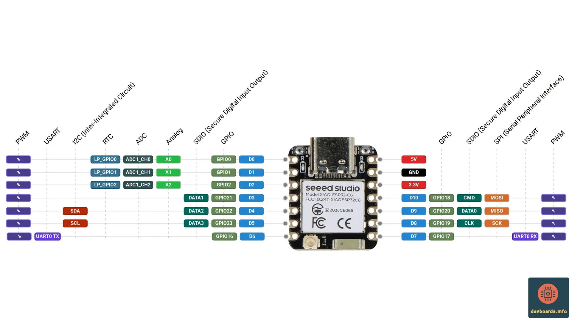
The XIAO ESP32C6 is the wireless-mesh member of the Seeed Studio XIAO family. It keeps the thumb-sized 21 x 17.8 mm XIAO outline and the single-sided component layout, and is built on the Espressif ESP32-C6 SoC with 512 KB of SRAM and 4 MB of flash.
The ESP32-C6 combines two 32-bit RISC-V processors: a high-performance core running at up to 160 MHz and a low-power core clocked at up to 20 MHz. Its radio covers 2.4 GHz Wi-Fi 6 (802.11ax), Bluetooth LE 5.3 and IEEE 802.15.4, so the board speaks Zigbee and Thread as well as Wi-Fi, and is Matter native. According to Seeed, it is the first XIAO member compatible with Thread.
Key features of the XIAO ESP32C6 pinout include:
- ESP32-C6 SoC with two 32-bit RISC-V cores, up to 160 MHz and up to 20 MHz
- 512 KB SRAM and 4 MB flash
- 2.4 GHz Wi-Fi 6 (802.11ax), Bluetooth LE 5.3, Zigbee 3.0 and Thread 1.3 over IEEE 802.15.4, with native Matter support
- Built-in ceramic antenna with a range of up to 80 m, and a U.FL connector for an external antenna
- 11 digital I/O pins at 3.3 V, three of them connected to ADC channels
- 1 x UART, 1 x LP_UART, 1 x I2C, 1 x LP_I2C, 1 x SPI and 1 x SDIO
- USB Type-C for power, programming and battery charging
- Built-in power management chip that charges a 3.7 V lithium battery, with a red charge LED
- Reset and Boot buttons, and a user LED on GPIO15
- Four power modes, with deep sleep down to 15 uA
XIAO ESP32C6 Technical Specification
| Platform | |
|---|---|
| Manufacturer | Seeed Studio |
| Processor | ESP32-C6 |
| Processor Family | RISC-V |
| Clock Speed | 160 MHz |
| Flash Memory | 4 MB |
| SRAM | 512 KB |
| I/O | |
|---|---|
| Digital I/O | 11 |
| Analog Input | 6 |
| PWM | 11 |
| ADC Resolution | 4096 |
| Interrupts | 11 |
| Power | |
|---|---|
| Input Voltage | 5 V |
| I/O Voltage | 3.3 V |
| I/O Current |
| Communication Protocols | |
|---|---|
| I2C | 2x |
| SPI | 1x |
| UART | 2x |
| Connectivity | |
|---|---|
| USB Type C | 1x |
| WiFi | 802.11b 802.11g 802.11n 802.11ax |
| Bluetooth | 5.3 Bluetooth LE 5.3 with Bluetooth Mesh |
| Zigbee | Zigbee 3.0 Coordinator, Router, End Device |
| Matter | over Wi-Fi, Thread |
| Peripherals | |
|---|---|
| RTC | 1x 48 bit |
| Timer | 2x 54 bit 1x 52 bit |
| Watchdog Timer | 3 |
| Cryptography | AES/DS/ECC/HMAC/RSA/SHA Accelerator |
| Debug/Trace | JTAG |
| Dimensions | |
|---|---|
| Width | 21 mm |
| Length | 17.8 mm |
XIAO ESP32C6 Pin Headers and Components
The XIAO ESP32C6 keeps the classic XIAO form factor: everything is mounted on the top side, the pads run along the two long edges, and the back carries the battery and test pads.
Dimensions
The board measures 21 x 17.8 mm, the same outline as the other XIAO boards. Seeed rates it for operation from -40 degrees C to 85 degrees C.
Castellated pads
The 14 castellated pads in the XIAO ESP32C6 pinout are the standard XIAO set: D0 to D6 on one edge, and 5V, GND, 3V3, D10, D9, D8 and D7 on the other. The board can be soldered directly onto a carrier PCB or fitted with pin headers.
USB Type-C connector
The USB Type-C connector is wired to the ESP32-C6's built-in USB Serial/JTAG controller. It powers the board, charges a connected battery, and carries programming and serial communication.
Antennas and the RF switch
The board has a ceramic antenna printed on the module end and a U.FL connector for an external antenna. An RF switch selects between them: GPIO3 must first be driven low to power the switch, and GPIO14 then selects the antenna, low for the built-in ceramic antenna (the default) and high for the external one. Seeed quotes up to 80 m of Wi-Fi and Bluetooth LE range with the on-board antenna.
Reset and Boot buttons
The Reset button pulls the chip's CHIP_PU (EN) line low to restart the ESP32-C6. The Boot button is connected to GPIO9, a strapping pin: holding it while the board powers up starts the chip in bootloader mode.
LEDs
The user LED is connected to GPIO15, which the Arduino core defines as LED_BUILTIN. A second, red LED is driven by the battery charger and reports charging state.
Pads on the back
The back of the board carries the battery pads and the JTAG test pads MTDO (GPIO7), MTDI (GPIO5), MTCK (GPIO6) and MTMS (GPIO4), along with an EN pad. A large thermal pad sits in the middle.
Note that several signals are not on any edge pad: GPIO3 and GPIO14 drive the RF switch, GPIO15 drives the user LED, GPIO9 is the Boot button, and GPIO4 to GPIO7 are the JTAG pads on the back.
Powering XIAO ESP32C6
The XIAO ESP32C6 runs from 5 V over USB Type-C or from a 3.7 V lithium battery. A built-in power management chip produces the 3.3 V rail, switches between the two sources, and charges the battery whenever USB is connected.
USB Type-C
USB is the usual supply: 5 V into the regulator, and the same input feeds the battery charger. Seeed lists the Type-C input voltage as 5 V and the battery input as 3.7 V.
5V pin
The 5V pin in the XIAO ESP32C6 pinout is connected to the USB VBUS line, so it outputs 5 V while the board is plugged into USB and can also be used as a power input. When the board runs from its battery, there is no voltage on the 5V pin.
3V3 pin
3V3 is the output of the on-board regulator, the rail the ESP32-C6 itself runs on, and can power external 3.3 V circuits.
GND pin
GND is the common ground for power, data and signals.
Battery pads
A rechargeable 3.7 V lithium battery solders to the two pads on the back. Seeed places the negative pad on the left, near the D8 silk screen marking, and the positive pad on the right, near the D5 marking, so check the polarity before soldering.
The red charge LED reports the charger's state: with no battery connected it lights when the Type-C cable is plugged in and turns off after 30 seconds; with a battery connected it flashes while charging and turns off once the battery is full.
Reading the battery voltage
There is no built-in battery measurement on this board. Seeed's wiki describes soldering a 200k resistor to form a 1:2 divider onto the A0 pin, then doubling the value read there to recover the battery voltage.
Power consumption
Seeed lists the following typical figures, measured with a 3.8 V supply:
- Modem-sleep: 30 mA
- Light-sleep: 3.1 mA
- Deep sleep: 15 uA
XIAO ESP32C6 Pinout and Peripherals
All peripherals come from the ESP32-C6. Its GPIO matrix can route most digital functions to almost any pin, so the functions below are the defaults used by the Arduino core and by Seeed's pin map. Of the chip's GPIO, 11 reach the castellated pads.
Digital GPIO
The XIAO ESP32C6 pinout has 11 digital I/O pins, D0 to D10, all using 3.3 V logic. Every one can drive PWM output through the chip's LED PWM controller and act as an interrupt source. Each pad maps to a fixed GPIO number:
- D0 — GPIO0, also A0 / ADC1_CH0 and LP_GPIO0
- D1 — GPIO1, also A1 / ADC1_CH1 and LP_GPIO1
- D2 — GPIO2, also A2 / ADC1_CH2 and LP_GPIO2
- D3 — GPIO21, SPI chip select (SS) in the Arduino core
- D4 — GPIO22, I2C SDA
- D5 — GPIO23, I2C SCL
- D6 — GPIO16, UART0 TX
- D7 — GPIO17, UART0 RX
- D8 — GPIO19, SPI SCK
- D9 — GPIO20, SPI MISO
- D10 — GPIO18, SPI MOSI
Analog to Digital Converter (ADC)
The ESP32-C6 has one 12-bit SAR ADC with seven channels, six of which reach a pad on the XIAO ESP32C6. Three are on the castellated edge pads: D0, D1 and D2, which the Arduino core also names A0, A1 and A2 and which are ADC1 channels 0, 1 and 2. The other three are on the back solder pads, where MTMS, MTDI and MTCK carry ADC1 channels 4, 5 and 6. The remaining channel is on GPIO3, which the board uses to enable the RF antenna switch and brings out to no pad.
Low-power I/O
D0, D1 and D2 are also LP_GPIO0 to LP_GPIO2, the low-power I/O pins the LP RISC-V core and the LP peripherals can use while the high-performance core sleeps.
UART
The default serial pins are D6 (UART0 TX, GPIO16) and D7 (UART0 RX, GPIO17). The chip additionally has a low-power LP_UART that keeps running in the low-power domain.
I2C
The default I2C bus uses D4 (SDA, GPIO22) and D5 (SCL, GPIO23). As with the UART, the chip also has a low-power LP_I2C controller.
SPI
The general-purpose SPI bus uses D8 (SCK, GPIO19), D9 (MISO, GPIO20) and D10 (MOSI, GPIO18). The Arduino core defines the default chip select SS on GPIO21, which is the D3 pad.
SDIO
Seeed's specification table lists one SDIO interface, and its pin map gives D3, D4 and D5 the alternate functions SDIO_DATA1, SDIO_DATA2 and SDIO_DATA3.
Wi-Fi, Bluetooth, Zigbee and Thread
The ESP32-C6 provides 2.4 GHz Wi-Fi 6 (802.11ax, and compatible with 802.11b/g/n), Bluetooth LE 5.3 with Bluetooth Mesh, and an IEEE 802.15.4 radio that carries Zigbee 3.0 and Thread 1.3. The three share one antenna, which is why the board needs the GPIO3 and GPIO14 RF switch to choose between the ceramic and the U.FL antenna. This mix is what makes the board Matter native, and, as Seeed puts it, the first XIAO compatible with Thread.
JTAG and debugging
The MTCK, MTDO, MTDI and MTMS pads on the back expose GPIO6, GPIO7, GPIO5 and GPIO4 for an external JTAG probe. The chip also has a built-in USB Serial/JTAG controller on the USB Type-C connector, so debugging over USB needs no extra hardware.
Timers and security
The ESP32-C6 provides two 54-bit general-purpose timers, a 52-bit system timer, three digital watchdog timers and an analog watchdog timer, plus hardware accelerators for AES, SHA, RSA, ECC, HMAC and digital signatures, a random number generator, secure boot and flash encryption.
Programming XIAO ESP32C6
- Arduino IDE: Espressif's Arduino-ESP32 core, version 3.0.0 or newer, includes a dedicated XIAO_ESP32C6 variant with the D0 to D10 pin names, the user LED and the RF switch pins.
- Arduino CLI: The same Arduino-ESP32 core and board definition can be used from the command line.
- MicroPython: MicroPython's ESP32 port carries a SEEED_XIAO_ESP32C6 board definition, so the board can be programmed in Python.
- CircuitPython: CircuitPython supports the board as seeed_xiao_esp32c6, as another way to program it in Python.
Related Development Boards
Like the XIAO ESP32C6 pinout?
We publish new board pinouts every week, with interactive diagrams, specs compared, and quick-start tips. No filler, unsubscribe anytime.
Join makers and engineers who follow devboards.info