The Arduino Pro Mini is a tiny board based on the ATmega328P operating at 16 MHz. It has 32 Kbytes of Flash, 2 Kbytes of SRAM and 1 Kbytes EEPROM.
Arduino Pro Mini Pinout includes 14 digital I/O pins, 6 analog inputs and 6 PWMs. It supports TWI (I2C), SPI, UART and 10-bit ADC.
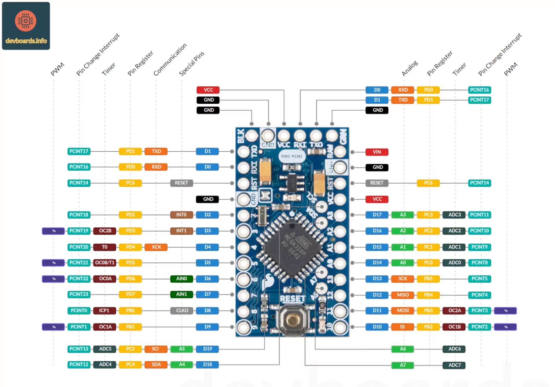
The board is available in two versions: 5V and 3.3V (with 8 MHz clock). As shown in Arduino Pro Mini Pinout, it doesn't have any port. This means that an external USB to serial adapter is needed to program it.
Manufacturer | Arduino |
Processor | ATmega328P |
Processor Family | AVR |
Clock Speed | 16 Mhz (8 Mhz on 3.3 V version) |
Flash Memory | 32 KB |
SRAM | 2 KB |
EEPROM | 1 KB |
Digital I/O | 14 |
Analog Input | 6 |
PWM | 6 |
ADC Resolution | 1024 |
Interrupts | 2 |
Input Voltage | 5-12 V (3.3-12 V on 3.3 V version) |
I/O Voltage | 5 V or 3.3 V (depending on the model) |
I/O Current | 40 mA |
I2C | 1x |
SPI | 1x |
UART | 1x |
Timer | 2x 8 bit 1x 16 bit |
Watchdog Timer | 1 |
Width | 17.5 mm |
Length | 33 m |
The Arduino Pro Mini is a compact, breadboard-friendly microcontroller based on the ATmega328P microcontroller. Unlike many other Arduino boards, the Pro Mini lacks onboard USB functionality, giving it a low-profile design suited for embedded applications. Here are the key physical components and pin headers visible on the board:
Dimensions
The board measures 51mm x 21mm.
Microcontroller (ATmega328P)
At the core of the Arduino Pro Mini is the ATmega328P, an 8-bit microcontroller that operates at either 5V (16 MHz model) or 3.3V (8 MHz model). This microcontroller manages all processing and control operations on the board.
Digital Input/Output Pins
The board includes 14 digital I/O pins which can be configured as either input or output. Each pin can provide or receive a maximum of 40 mA of current, suitable for driving LEDs or reading signals from switches. Six of these pins support PWM, which is often used for controlling motor speed, LED brightness, and simulating analog outputs.
Analog Input Pins
The Pro Mini has six analog input pins labeled A0 to A5. These pins allow for the reading of analog signals with a resolution of 10 bits (values ranging from 0 to 1023). Common uses for these pins include reading data from sensors like temperature sensors, potentiometers, and light sensors.
Reset Button
Located on the surface of the board, the reset button allows the user to reset the microcontroller. This action stops any current program and restarts the board, which is especially helpful during debugging or code upload.
Programming Header
The Arduino Pro Mini does not include onboard USB connectivity, so programming requires an external USB-to-serial adapter. The 6-pin header (labeled GND, VCC, RXI, TXO, DTR, and another GND) allows users to connect an external FTDI or CP2102 module to upload code from the Arduino IDE.
The minimal layout of the Arduino Pro Mini gives it flexibility and makes it ideal for space-constrained projects. The pin headers offer essential connectivity, while the absence of onboard USB and other larger components maintains its compact, low-power design.
The Arduino Pro Mini offers versatile power options, making it adaptable to different project requirements. Here are the primary ways to power the Arduino Pro Mini:
RAW/VIN Pin
The RAW pin is an unregulated power input designed to accept higher voltages and route them through an onboard voltage regulator to output a stable voltage to the microcontroller and other components.
VCC Pin
The VCC pin is a regulated voltage input and output, depending on the source. When connected to an external 3.3V or 5V supply, the VCC pin provides stable power to the microcontroller, bypassing the onboard regulator.
FTDI USB-to-Serial Adapter
The Arduino Pro Mini lacks an onboard USB port, but it can be powered and programmed via an external FTDI or USB-to-serial adapter. When connected to a USB adapter, the adapter’s VCC line powers the board at 5V or 3.3V, depending on the adapter and Pro Mini version.
The Arduino Pro Mini, powered by the ATmega328P microcontroller, includes several built-in peripherals, enabling it to interface with various sensors, actuators, and communication modules. Here is a breakdown of the key peripherals available:
Digital Input/Output (I/O) Pins
The Arduino Pro Mini pinout includes 14 digital I/O pins that can be configured as either input or output in the Arduino IDE, making them suitable for reading digital signals (like switches).
ADC (Analog-to-Digital Converter)
The six analog input pins are connected to the 10-bit ADC, translating analog signals into digital values ranging from 0 to 1023. These are typically used for interfacing with analog sensors, like temperature sensors or potentiometers.
Timers
There are three timers on Arduino Pro Mini that are used to count intervals or generate PWM signals. Timer0 and Timer2 are 8-bit timers, while Timer1 is a 16-bit timer. They enable various functions, including time tracking, delays, and waveform generation for PWM output.
Serial Communication (UART)
The single UART (Universal Asynchronous Receiver-Transmitter) interface allows serial communication between the Pro Mini and other devices, such as a computer or another microcontroller. This is typically used for programming the Pro Mini through a USB-to-serial adapter and for sending data to other serial devices.
I2C (Inter-Integrated Circuit)
The I2C interface is a 2-wire communication protocol commonly used for connecting multiple sensors or peripherals using only two pins: SDA (data line) and SCL (clock line). It is widely supported and allows the Pro Mini to communicate with devices like temperature sensors, displays, and EEPROMs.
SPI (Serial Peripheral Interface)
The Arduino Pro Mini has one SPI interface that can be used for connecting devices like SD cards, certain displays, and RF modules.
Watchdog Timer
The watchdog timer is a safety feature that resets the microcontroller if it becomes unresponsive. It is particularly useful in autonomous applications to ensure the microcontroller recovers from unexpected errors.
External Interrupts
As shown in the Arduino Pro Mini pinout, there are two pins that support the external interrupt. This allows the microcontroller to immediately respond to specific events, such as a button press or signal change from an external sensor, without waiting for the main program loop.
These built-in peripherals make the Arduino Pro Mini capable of handling a variety of embedded applications, from sensor monitoring to actuator control, with easy interfacing for communication and timing functionalities.
Programming the Arduino Pro Mini is slightly different from other Arduino boards because it lacks a built-in USB interface. The Pro Mini is typically connected to the computer through a USB-to-Serial adapter, such as an FTDI module, CP2102, or CH340G, to handle data transmission between the computer and board. There are several accessible methods to program this board, using standard Arduino tools and programming languages. Here are the main options:
These programming methods make the Arduino Pro Mini a versatile microcontroller board that’s adaptable to different levels of programming needs, from basic Arduino IDE use to advanced embedded C/C++ programming.