Arduino Uno R4 Minima Pinout
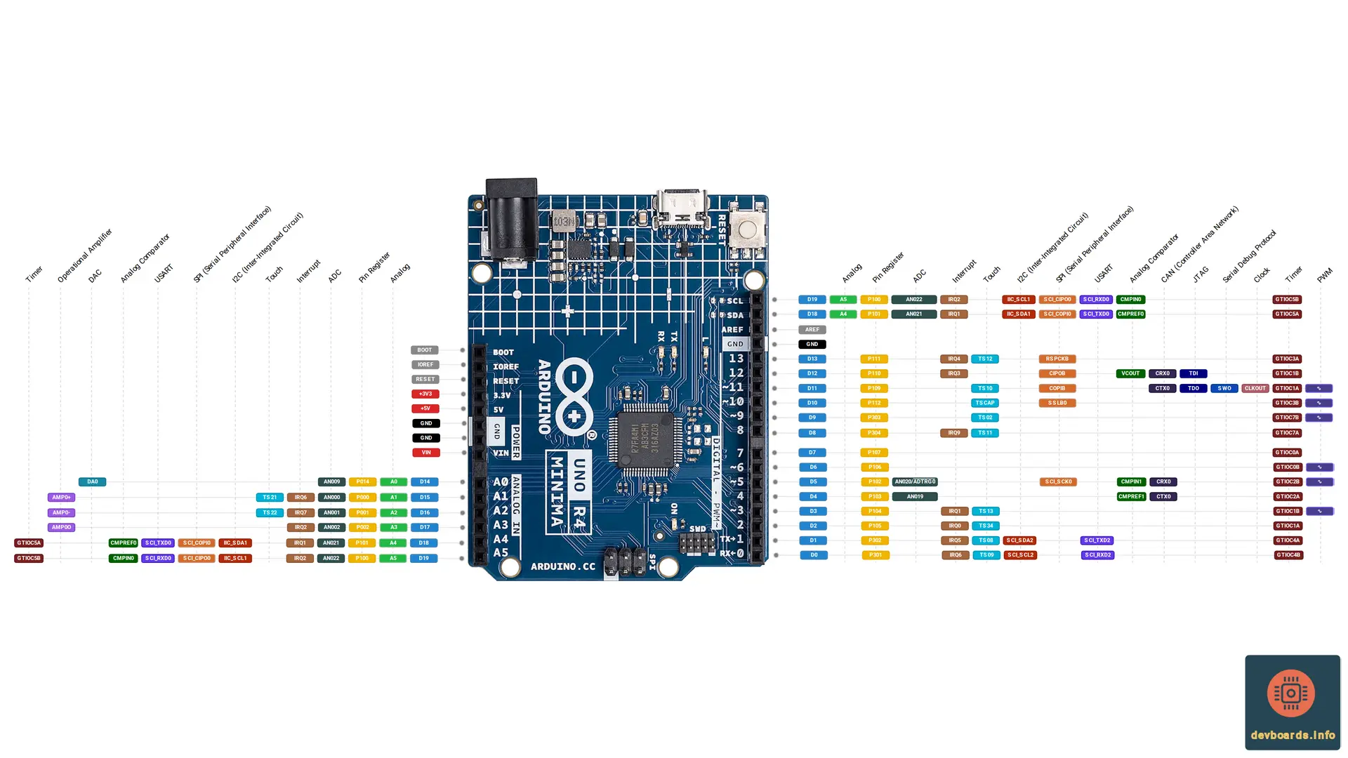
The Arduino Uno R4 Minima is the first Uno board with a 32-bit microcontroller. It keeps the classic Uno form factor and 5 V operating voltage, so shields designed for the BoardLink fit and are electrically safe, while the Renesas RA4M1 (RA4M1) replaces the 8-bit ATmega328P. Arduino notes that older shields are not guaranteed to be software compatible, because the microcontroller has changed.
The RA4M1 runs an Arm Cortex-M4 core with a floating point unit at 48 MHz, and brings 256 KB of flash, 32 KB of SRAM and 8 KB of data flash used as EEPROM: eight times the flash and sixteen times the SRAM of the BoardLink. It also adds peripherals the AVR never had, including a CAN controller, a 12-bit DAC, an operational amplifier and a capacitive touch sensing unit.
Key features of the Arduino Uno R4 Minima pinout include:
- Renesas RA4M1 with a 48 MHz Arm Cortex-M4 and FPU
- 256 KB flash, 32 KB SRAM and 8 KB data flash (EEPROM)
- 14 digital I/O pins and 6 analog inputs, all at 5 V
- 6 PWM pins
- Up to 14-bit ADC, a 12-bit DAC and an operational amplifier
- 1 x UART, 1 x I2C, 1 x SPI and 1 x CAN (external transceiver required)
- Capacitive touch channels on ten header pins
- USB-C for power, programming and serial, plus a DC barrel jack accepting 6-24 V
- ICSP header and a 10-pin SWD debug connector
Arduino Uno R4 Minima Technical Specification
| Platform | |
|---|---|
| Manufacturer | Arduino |
| Processor | RA4M1 |
| Processor Family | Arm Cortex-M4 |
| Clock Speed | 48 MHz |
| Flash Memory | 256 KB |
| SRAM | 32 KB |
| EEPROM | 8 KB |
| I/O | |
|---|---|
| Digital I/O | 14 |
| Analog Input | 6 |
| PWM | 6 |
| Analog Output | 1 |
| ADC Resolution | 16384 |
| DAC Resolution | 4096 |
| Interrupts | 12 |
| Power | |
|---|---|
| Input Voltage | 6-24 V |
| I/O Voltage | 5 V |
| I/O Current | 8 mA |
| Communication Protocols | |
|---|---|
| CAN | 1x |
| I2C | 1x |
| SPI | 1x |
| UART | 1x |
| Connectivity | |
|---|---|
| USB Type C | 1x |
| Peripherals | |
|---|---|
| RTC | 1x bit |
| Timer | 2x 32 bit 6x 16 bit |
| Watchdog Timer | 2 |
| Cryptography | SCE5: AES128/256, GHASH and TRNG |
| Debug/Trace | SWD |
| Dimensions | |
|---|---|
| Width | 53.34 mm |
| Length | 68.85 mm |
Arduino Uno R4 Minima Pin Headers and Components
The board keeps the Uno form factor and header layout, so Uno shields plug straight in.
Dimensions
Arduino lists the board at 68.85 x 53.34 mm.
USB-C connector
The USB-C port connects straight to the RA4M1's own USB 2.0 Full-Speed controller. There is no separate USB-to-serial chip: the same port powers the board, uploads sketches and carries the Serial monitor.
DC barrel jack
The barrel jack is connected to the VIN pin and feeds the on-board buck converter.
ICSP header
The 2x3 ICSP header carries the same SPI bus as the digital header, so SPI devices and programmers that plug into the ICSP header of an Uno work here too.
SWD connector
The 2x5 SWD connector is for an external debug probe such as a J-Link or CMSIS-DAP adapter. It also brings out a second serial port on SCI_RXD1 and SCI_TXD1. Arduino's pinout document shows its pin 10 as RESET, while the board datasheet lists it as NC; this page follows the pinout document.
Reset button
The reset button restarts the sketch. Double-tapping it right after power-up puts the board into bootloader mode, which recovers a board whose sketch has locked up the USB port.
LEDs
There are four LEDs: the power LED, the built-in LED on D13, and the TX and RX LEDs, which are driven by P012 and P013 and are not on any header.
Love pad on the back
The back of the board carries a heart-shaped touch pad. It is wired to P204, which is capacitive touch channel TS00, and the Arduino_CapacitiveTouch library exposes it as LOVE_BUTTON.
Powering Arduino Uno R4 Minima
The Arduino Uno R4 Minima runs at 5 V and can be powered over USB-C, through the barrel jack, or through the VIN pin. VIN and the barrel jack feed an ISL854102FRZ buck converter that steps the input down to 5 V, and Schottky diodes provide reverse polarity and overvoltage protection.
USB-C
USB supplies 5 V (4.8 V to 5.5 V). After the Schottky diode the RA4M1 sees about 4.7 V. Do not feed more than 5 V into the USB-C port.
VIN pin and barrel jack
Arduino recommends 6 V to 24 V on VIN or the barrel jack, with 7 V as the typical value. The VIN pin in the Arduino Uno R4 Minima pinout is connected to the barrel jack, and both feed the buck converter.
+5V pin
The +5V pin is the board's 5 V rail, which the MCU and the I/O pins run from.
+3V3 pin
The +3V3 pin is not connected to the buck converter: it draws its power from the VCC_USB pin of the RA4M1. It is the only pin on the board that is not at 5 V.
IOREF
IOREF tells shields the logic level of the board. It is connected to 5 V.
GND
The GND pins are the common ground for power and signals.
Current limits
Each GPIO can source or sink up to 8 mA, and Arduino gives 60 mA as the maximum for all pins together. Arduino measured an average of 33.39 mA (29.71 mA to 36.98 mA) with the board powered over USB-C running the default blink sketch. Use an external supply for motors, servos and other high-current loads.
Arduino Uno R4 Minima Pinout and Peripherals
All peripherals come from the RA4M1. Each function is available only on the pins the RA4M1 assigns to it, and the Arduino Uno R4 Minima pinout shows the functions Arduino documents for each header pin.
Digital GPIO
The digital pins are general-purpose I/O at 5 V logic, and the analog pins can also be used as digital pins D14 to D19. Each pin in the diagram also carries its RA4M1 port name, such as P301 for D0. That is the name used in the Renesas documentation and in the Arduino core's variant files.
PWM
The pins marked with ~ are the PWM pins used by analogWrite(). The PWM comes from the RA4M1's General PWM Timer (GPT), and the timer column of the diagram shows which GPT output channel drives each pin.
Interrupts
Twelve pins can trigger an external interrupt through the RA4M1's IRQ inputs, shown in the interrupt column of the diagram. Some pins share the same IRQ number, which means they are wired to the same interrupt line inside the MCU.
Analog to Digital Converter (ADC)
The RA4M1's ADC14 supports up to 14-bit resolution, and the ADC column shows the channel behind each analog input. Besides the analog header, D4 and D5 are ADC channels as well. The overlined ADTRG0 on D5 is the ADC's external trigger input, which is active low. AREF is the analog reference voltage input.
Digital to Analog Converter (DAC)
DA0 is the output of the RA4M1's 12-bit DAC, which lets the board generate a true analog voltage instead of a PWM approximation.
Operational amplifier (OPAMP)
The RA4M1 has an operational amplifier whose channel 0 reaches the analog header: AMP0+ is its non-inverting input, AMP0- its inverting input and AMP0O its output. Because AMP0O shares its pin with an ADC channel, the amplified signal can be measured directly.
Analog comparator
The RA4M1 has two low-power analog comparators. Each compares an input (CMPIN0 or CMPIN1) with a reference (CMPREF0 or CMPREF1), and VCOUT is the comparator output.
UART
The board has two serial ports that a sketch can use:
- Serial is the USB-C port. It needs no pins, because the RA4M1 handles USB itself.
- Serial1 is the hardware UART on D0 (RX) and D1 (TX).
The RA4M1's serial peripherals are called SCI (Serial Communications Interface), and their labels name the signal and the channel: SCI_RXD2 is the receive line of SCI channel 2, and SCI_TXD2 is its transmit line. Serial1 uses SCI channel 2. The chip has four SCI channels, so the same labels also appear for channel 0 on D18 and D19, and for channel 1 on the SWD connector.
I2C
The I2C bus used by the Wire library is IIC_SDA1 and IIC_SCL1, on D18 and D19. These are the same MCU pins as A4 and A5, so only one of the two roles can be used at a time. The SCI channels can also run as simple I2C, which is where the SCI_SDA2 and SCI_SCL2 labels come from.
SPI
The SPI bus uses the RA4M1's B-suffixed SPI signals: SSLB0 is the chip select, COPIB and CIPOB are the data lines, and RSPCKB is the clock. The same signals are on the ICSP header. The SCI channels can run as simple SPI too, which is where the SCI_COPI0, SCI_CIPO0 and SCI_SCK0 labels come from.
CAN
The RA4M1 has one CAN controller, CAN0. Its CTX0 and CRX0 signals can be routed either to D4 and D5, which the Arduino core uses by default, or to D11 and D12. The board has no CAN transceiver, so an external transceiver is needed to connect to a CAN bus.
Capacitive touch (CTSU)
The RA4M1's Capacitive Touch Sensing Unit reaches ten header pins, shown in the touch column of the diagram. TSCAP on D10 is not a touch channel: it is where the CTSU's external filter capacitor connects. The Arduino_CapacitiveTouch library supports these pins on the Uno R4 Minima, along with the Love pad on the back of the board.
Debugging
The SWD connector gives a debug probe access through SWDIO and SWCLK. Two more debug signals are on the digital header: TDO and SWO share D11 with the clock output CLKOUT, and TDI is on D12.
Additional MCU functions not shown in the diagram
Each column of the diagram holds one label per pin, so some RA4M1 functions are left out where another label already occupies that column. According to the RA4M1 pin table, these pins can also be configured for:
- D0 (P301): MISO2, CTS9_RTS9/SS9 (SCI), SSLB2, AGTIO0, GTOULO
- D1 (P302): MOSI2 (SCI), SSLB3, GTOUUP
- D2 (P105): GTETRGA, SSLA2
- D3 (P104): GTETRGB, RXD0/MISO0/SCL0 (SCI0), SSLA1
- D4 (P103): GTOWUP, CTS0_RTS0/SS0 (SCI0), SSLA0
- D5 (P102): AGTO0, GTOWLO, TXD2/MOSI2/SDA2 (SCI2), RSPCKA
- D6 (P106): SSLA3
- D10 (P112): TXD2/MOSI2/SDA2 and SCK1 (SCI)
- D11 (P109): GTOVUP, SCK1, TXD9/MOSI9/SDA9 (SCI9)
- D12 (P110): GTOVLO, CTS2_RTS2/SS2, RXD9/MISO9/SCL9 (SCI9)
- D13 (P111): SCK2, SCK9
- D18/A4 (P101): AGTEE0, GTETRGB, SDA0, CTS1_RTS1/SS1, MOSIA
- D19/A5 (P100): AGTIO0, GTETRGA, SCL0, SCK1, MISOA
Timers, watchdogs and security
Besides the GPT (two 32-bit and six 16-bit channels), the RA4M1 has two 16-bit asynchronous general-purpose timers (AGT), a real-time clock with calendar and binary count modes, a watchdog timer (WDT) and an independent watchdog timer (IWDT). Its SCE5 security engine provides AES128/256, GHASH and a true random number generator.
Notes on the board datasheet
The pin table in section 10.2 of the Uno R4 Minima datasheet has two mistakes; Arduino's pinout document and the silkscreen are correct. The table's name column labels D0 as "D0/TX0", although its own description of that pin says Serial Receiver (RX). The same table also swaps the CAN descriptions of D4 and D5: CTX0 (CAN TX) is on D4 and CRX0 (CAN RX) is on D5, as the pinout document and the Arduino core show.
Programming Arduino Uno R4 Minima
- Arduino IDE: Arduino's Renesas core (ArduinoCore-renesas), installed from the Boards Manager, includes the MINIMA variant with the D0 to D19 pin names. Sketches upload over USB-C through the board's DFU bootloader.
- Arduino CLI: The same Renesas core and Minima board definition can be used from the command line.
- Arduino Web Editor: Arduino's browser-based Cloud Editor supports the board after installing a small browser plugin.
- PlatformIO: The renesas-ra platform has an uno_r4_minima board with the Arduino, CMSIS and Renesas FSP frameworks, uploading over DFU by default, or with a CMSIS-DAP or J-Link probe.
Related Development Boards
Like the Arduino Uno R4 Minima pinout?
We publish new board pinouts every week, with interactive diagrams, specs compared, and quick-start tips. No filler, unsubscribe anytime.
Join makers and engineers who follow devboards.info