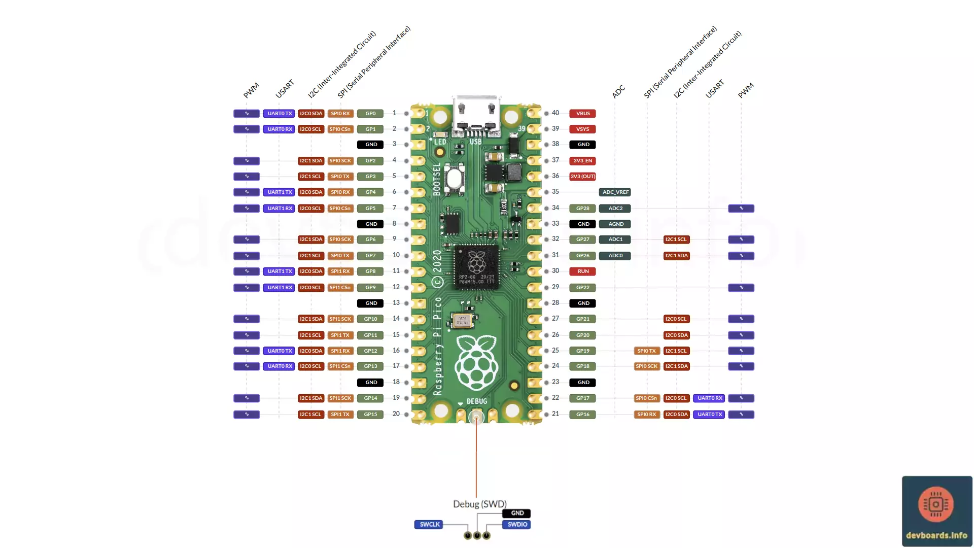
The Raspberry Pi Pico is a compact and versatile microcontroller development board based on the RP2040 chip. The Raspberry Pi Pico offers a balance of performance, low power consumption, and affordability. With dual-core Arm Cortex-M0+ processors, flexible I/O options, and support for multiple programming languages like C, C++, and MicroPython, the Pico opens up a range of possibilities for creating interactive and intelligent devices. Some major features include:
Manufacturer | Raspberry Pi |
Processor | RP2040 |
Processor Family | Arm Cortex-M0+ |
Clock Speed | 125 Mhz |
Flash Memory | 2 MB |
SRAM | 264 K |
Digital I/O | 26 |
Analog Input | 3 |
PWM | 16 |
ADC Resolution | 4096 |
Interrupts | 26 |
Input Voltage | 5V |
I/O Voltage | 3.3V |
I/O Current | 12 mA |
I2C | 2x |
SPI | 2x |
UART | 2x |
USB Micro B | 1x |
RTC | 1x 32 bit |
Timer | 1x 64 bit |
Watchdog Timer | 1 |
Debug/Trace | SWD |
Width | 21 mm |
Length | 51 mm |
Weight | 10 g |
The Raspberry Pi Pico is a compact microcontroller board with various components and headers that make it versatile and easy to use for different projects. Below are the key element of the board you may be interested to know about:
Dimensions
The board measures 51mm x 21mm.
Pin Headers (GPIO Pins)
The Raspberry Pi Pico has 40 pins in total, arranged in two rows of 20 pins each.
Micro-USB Port
The micro-USB port, located at the edge of the board, is the primary way to connect the Raspberry Pi Pico to a computer for power and programming. It’s compatible with a standard micro-USB cable and handles data and power input (5V).
Bootsel Button
This small button is used to enter programming mode. By pressing and holding the Bootsel button while connecting the Pico to power, the board goes into USB mass storage mode, allowing you to upload firmware or access the file system.
LED Indicator
The Pico has a built-in LED that can be controlled via GPIO25. It is often used to provide visual feedback for various applications, such as status indication or testing purposes.
RP2040 Microcontroller Chip
The heart of the Raspberry Pi Pico, the RP2040, is a dual-core Arm Cortex-M0+ processor designed by Raspberry Pi. It powers the entire board and provides the processing capability for Pico’s operations.
Debug Header (SWD)
A small set of pads is available for Serial Wire Debug (SWD) access, which allows low-level debugging and direct communication with the RP2040 chip. Although not pre-soldered, these pads can be used by advanced users to connect external debuggers.
Test Pads
In the back of the board are various test pads allowing you to hook into different areas such as USB data pins, triggering boot select, or the LED pin.
The Raspberry Pi Pico offers a few flexible options for powering the board, making it suitable for various project setups. Here are the main ways to power the Pico:
Micro-USB Port
The simplest and most common way to power the Raspberry Pi Pico is via the micro-USB port. When connected to a computer or USB power adapter, the micro-USB provides a stable 5V input to the board. This port not only powers the board but also serves as the primary connection for programming and data transfer.
VBUS Pin
The VBUS pin is directly connected to the 5V power provided by the USB input. If your project requires direct access to the 5V input, you can use this pin to power additional external components. This pin outputs 5V only when the board is powered via the USB port.
VSYS Pin
The VSYS pin is the primary power input pin on the Pico, offering an alternative to the micro-USB port. This pin can accept a voltage range from 1.8V to 5.5V, making it compatible with various external power sources, such as batteries.
For example, a common power source like a 3.7V LiPo battery can connect directly to the VSYS pin.
3V3 (OUT) Pin
The 3V3 pin is an output from the Pico’s onboard voltage regulator, providing a stable 3.3V for other components or sensors in your circuit.
The onboard regulator converts the USB 5V or VSYS input to a stable 3.3V output, suitable for most low-power components used alongside the Pico.
GND Pins
Ground (GND) pins are available in multiple locations across the Pico’s pin headers. All external components that need a reference ground should be connected to any of these GND pins to complete the circuit.
External 3.3V Source
For advanced users, the Raspberry Pi Pico can be powered directly by supplying a 3.3V input on the 3V3 (OUT) pin. However, caution should be taken here as it bypasses the regulator, and any over-voltage could damage the board.
This option is mostly used when the Pico is part of a larger circuit with a commonly regulated 3.3V power source.
The Raspberry Pi Pico’s RP2040 microcontroller comes with a variety of built-in peripherals designed to support a wide range of applications. Here’s a breakdown of the main peripherals that are mostly available in Raspberry Pi Pico pinout on the board:
Digital GPIO Pins
The Pico has 26 General Purpose Input/Output (GPIO) pins, which can be configured for digital input or output. These pins offer high flexibility and can be programmed to perform various functions in custom circuits.
PWM (Pulse Width Modulation)
16 of the GPIO pins support PWM, enabling the generation of variable-width pulses. PWM is widely used for applications such as dimming LEDs, controlling motor speed, or generating audio signals.
I2C
The Pico includes two I2C controllers, allowing communication with I2C-compatible devices like sensors, displays, and EEPROMs. Each controller can communicate with multiple devices over a shared bus.
SPI (Serial Peripheral Interface)
The board provides two SPI controllers, ideal for high-speed communication with SPI-enabled peripherals. SPI is commonly used for fast data transfer with components like SD cards, displays, and certain sensors.
UART (Universal Asynchronous Receiver/Transmitter)
With two UART controllers, the Pico can handle serial communication with other devices that use standard serial protocol, such as GPS modules, Bluetooth modules, external microcontrollers, or computers.
ADC (Analog to Digital Converter)
The Pico includes 3 ADC channels, allowing it to measure analog signals from sensors and other components. Each ADC channel has a 12-bit resolution, which translates analog voltages into digital values.
PIO (Programmable I/O)
The RP2040 features two Programmable I/O (PIO) blocks, each with 4 state machines. These allow users to implement custom protocols and control signals that might not be natively supported by the other peripherals.
Timers
Multiple hardware timers on the RP2040 allow for precise control of timed events, such as delays, periodic interrupts, or time-sensitive applications.
USB 1.1 Controller
The RP2040 microcontroller includes a built-in USB 1.1 controller, enabling direct USB communication when connected to a computer. This controller supports USB Device Mode, allowing the Pico to emulate devices like keyboards, mice, or serial interfaces.
Programming the Raspberry Pi Pico offers multiple options, allowing developers to choose from a range of tools and languages that best suit their project needs and experience level. Here are the main programming options available for the Pico:
The BOOTSEL button is used to enter USB mass storage mode for firmware upload.
To update, press and hold BOOTSEL while connecting to USB, then drag and drop the new firmware file.
Yes, it can control motors through PWM output on its GPIO pins.
PIO blocks allow for custom hardware interfaces and protocols not natively supported by the RP2040.
Yes. The Real-time Clock (RTC) provides time in a human-readable format and can be used to generate interrupts at specific times
Yes, you can power the Pico with batteries using the VSYS pin. The board doesn’t have any charger circuit. So, you have to handle that via custom circuit yourself.
The RP2040 can run at a maximum clock speed of 133 MHz.
Each GPIO pin can handle up to 12 mA, with a maximum of 50 mA across all pins.
Yes, with Arduino IDE support, you can use many Arduino libraries with the Pico. But you have to check the documentation of each library to be sure the maintainer added support for the Raspberry Pi Pico.
It has 2 MB of onboard flash memory but no storage expansion slots.
To reset, press and hold the BOOTSEL button while connecting the Pico to power or use an external reset circuit.
Yes, lightweight models can be run using TensorFlow Lite for Microcontrollers.
No, the standard Raspberry Pi Pico does not have built-in wireless connectivity.