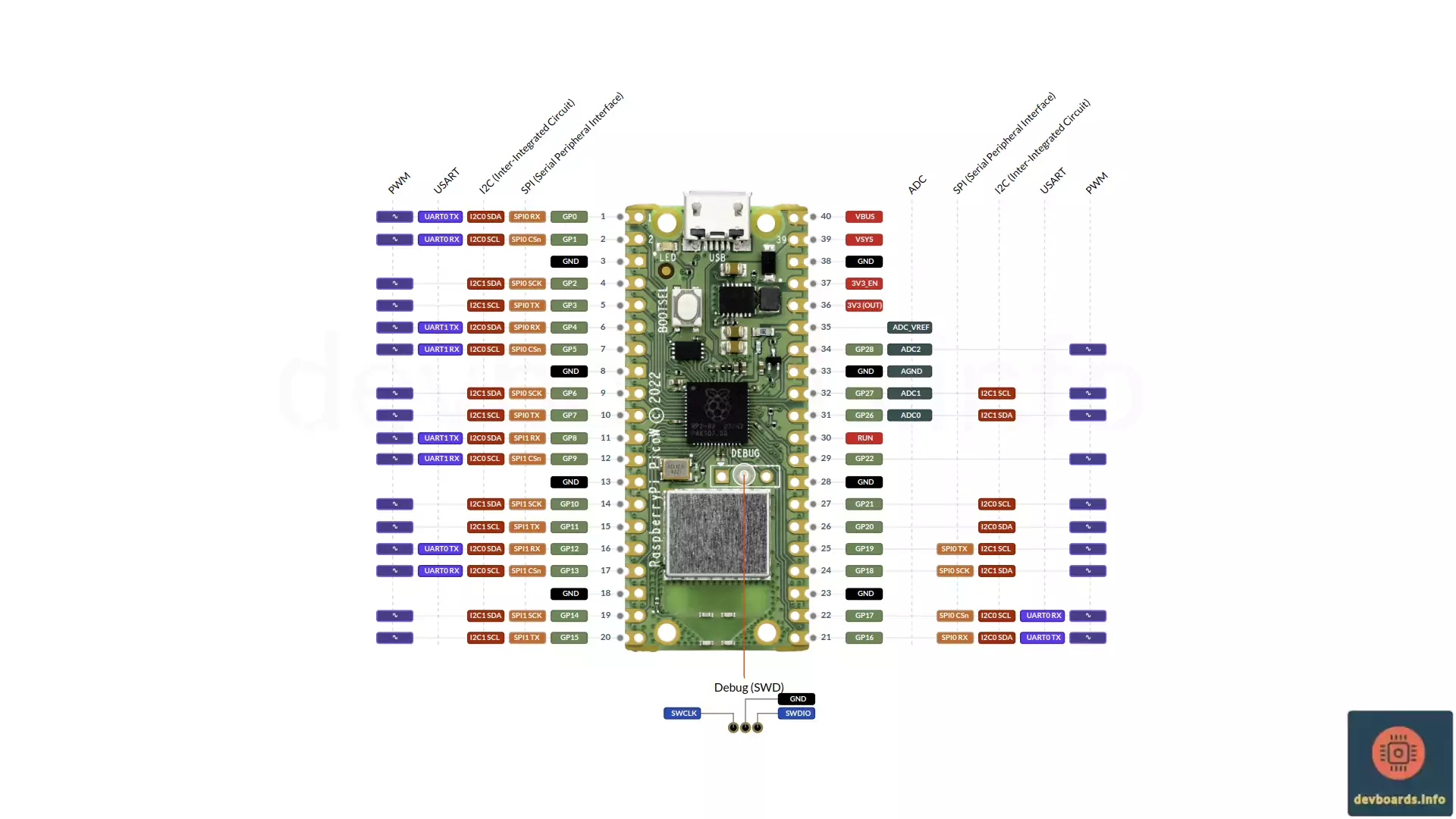
The Raspberry Pi Pico W is a variation of the Raspberry Pi Pico board, adding Wi-Fi connectivity to the platform. It retains the same core features and form factor as the original Pico, including the RP2040 microcontroller, dual-core Arm Cortex-M0+ processors, and 26 GPIO pins. The primary difference is the on-board 2.4GHz 802.11n wireless interface using an Infineon CYW43439 module.
It features flexible I/O options and support for multiple programming languages like C, C++, and MicroPython. Some of its major features include:
Manufacturer | Raspberry Pi |
Processor | RP2040 |
Processor Family | Arm Cortex-M0+ |
Clock Speed | 125 Mhz |
Flash Memory | 2 MB |
SRAM | 264 K |
Digital I/O | 26 |
Analog Input | 3 |
PWM | 16 |
ADC Resolution | 4096 |
Interrupts | 26 |
Input Voltage | 5V |
I/O Voltage | 3.3V |
I/O Current | 12 mA |
I2C | 2x |
SPI | 2x |
UART | 2x |
USB Micro B | 1x |
WiFi | 802.11n Provided by Infineon CYW43439 module |
Bluetooth | 5.2 Provided by Infineon CYW43439 module |
RTC | 1x 32 bit |
Timer | 1x 64 bit |
Watchdog Timer | 1 |
Debug/Trace | SWD |
Width | 21 mm |
Length | 51 mm |
Weight | 10 g |
The Raspberry Pi Pico W is a compact microcontroller board with integrated Wi-Fi and an easy-to-navigate layout, offering a range of pin headers and components to support wireless-enabled projects. Here’s a breakdown of the physical elements of the Pico W:
Dimensions
The board measures 51mm x 21mm.
Pin Headers
The Pico W has 40 pins arranged in two rows of 20 pins each, with a total of 26 multi-function GPIO (General Purpose Input/Output) pins.
Micro-USB Port
The micro-USB port located on the edge of the board is used to connect the Raspberry Pi Pico W to a computer for power and data transfer. Through this port, you can program the board and supply it with 5V.
Wi-Fi Module (Infineon CYW43439)
The Pico W includes an Infineon CYW43439 chip for Wi-Fi connectivity, adding wireless communication capabilities that are missing in the standard Raspberry Pi Pico. This module sits near the edge of the board and enables Wi-Fi functionality for IoT and remote projects.
Bootsel Button
This small button enables USB mass storage mode. By holding it down while connecting the Pico W to a power source, the board enters firmware loading mode, allowing for quick uploading of new code or software.
LED Indicator
The Pico W features a built-in LED that is connected to the WL_GPIO0 pin of the Infineon CYW43439 module. This LED provides visual feedback for programming and debugging purposes, such as indicating the board’s status in certain applications.
RP2040 Microcontroller
The RP2040chip, designed by Raspberry Pi, serves as the primary processor. It’s a dual-core Arm Cortex-M0+ processor that powers the board’s operations, including handling GPIO inputs and controlling peripherals.
Debug Header (SWD)
A set of pads located on the board provides access to Serial Wire Debug (SWD) functionality. This header is commonly used by advanced users for in-depth debugging and development at the chip level.
Wireless/Bluetooth Antenna
The antenna is connected to the Infineon CYW43439. Based on Raspberry Pi Pico W documentation, for best wireless performance, the antenna should be in free space.
The Raspberry Pi Pico W offers multiple options for powering the board, making it adaptable for a wide range of applications. Below are the main methods for providing power:
Micro-USB Port
The easiest way to power the Raspberry Pi Pico W is through its micro-USB port. When connected to a computer or USB power adapter, this port supplies a stable 5V input to the board.
In addition to powering the board, the micro-USB port enables data transfer and programming, making it a convenient choice for both development and operation.
VSYS Pin
The VSYS pin in Raspberry Pi Pico Pinout serves as the main power input pin. It can accept a wide voltage range from 1.8V to 5.5V, allowing flexibility in power sources, such as batteries.
This pin is useful for mobile or battery-operated projects, with a common choice being a 3.7V LiPo battery connected directly to the VSYS pin.
3V3 (OUT) Pin
The 3V3 (OUT) pin outputs a regulated 3.3V from the onboard regulator. It provides stable power to low-voltage components and external sensors, making it especially valuable in projects with multiple connected components.
This pin is powered through the micro-USB or VSYS input, and it serves as a regulated source for other devices connected to the Pico W.
VBUS Pin
The VBUS pin in the Raspberry Pi Pico W pinout outputs 5V when the Raspberry Pi Pico W is powered via the USB connection. This pin allows access to the USB’s 5V supply, which can be used to power external components.
The VBUS is active only when the micro-USB is connected and providing power, so it’s best suited for USB-powered projects.
GND Pins
Ground (GND) pins are located at multiple points across the Pico W’s pin headers. They provide a common return path for power and should be used to connect the ground of any external circuits or components to complete the power circuit.
External 3.3V Source
For advanced applications, the Pico W can be powered directly via an external 3.3V input, bypassing the onboard voltage regulator. This can be done by supplying a 3.3V input to the 3V3 (OUT) pin, although caution is advised as the board’s components depend on this regulated voltage.
This option is typically used only when integrating the Raspberry Pi Pico W into a larger 3.3V-regulated system, as over-voltage could damage the board.
The Raspberry Pi Pico W is built on the RP2040 microcontroller and includes a range of peripherals, expanding the board’s capabilities for various input/output and communication tasks. The addition of Wi-Fi connectivity further extends its usefulness for IoT and networked applications. Here’s a rundown of the key peripherals available on the Pico W as also shown on the Raspberry Pi Pico W pinout diagram.
Digital GPIO Pins
The Pico W has 26 General Purpose Input/Output (GPIO) pins that can be used for digital input or output operations. These pins can be programmed for a variety of tasks, from controlling LEDs to reading inputs from buttons.
Analog to Digital Converter (ADC)
The Pico W includes 3 ADC channels, allowing it to read analog signals from components like potentiometers, temperature sensors, and other analog devices. Each ADC channel has a 12-bit resolution, providing precise analog readings.
PWM (Pulse Width Modulation)
With 16 PWM channels available, the Pico W can generate variable-width pulses for applications that require adjustable output levels, such as dimming LEDs or controlling the speed of DC motors.
I2C
The board features two I2C controllers, allowing it to communicate with I2C-compatible devices like displays, sensors, and EEPROM modules. Each I2C controller supports multiple devices on the same bus.
SPI (Serial Peripheral Interface)
The Pico W has two SPI controllers, ideal for high-speed data communication with devices like SD cards, displays, or certain types of sensors.
UART (Universal Asynchronous Receiver/Transmitter)
Two UART controllers provide serial communication, enabling the Pico W to interface with GPS modules, Bluetooth modules, or other serial devices.
Programmable I/O (PIO)
The RP2040 microcontroller includes two PIO (Programmable I/O) blocks, each with four state machines. These blocks allow users to create custom protocols and signals that the standard GPIO cannot handle directly.
Timers
Multiple hardware timers in the RP2040 provide precise control over time-sensitive events, such as scheduling tasks, generating delays, or managing time-based outputs.
USB 1.1 Controller
The Pico W includes a USB 1.1 controller, which allows it to communicate with a computer when connected via USB. This controller can be used in USB Device Mode, letting the board emulate USB devices such as HID keyboards, serial interfaces, and more.
Infineon CYW43439 Wi-Fi Module
Unique to the Pico W, the Infineon CYW43439 module provides 802.11n Wi-Fi connectivity, allowing the board to connect to wireless networks. This feature opens up a range of possibilities for IoT applications, such as sending sensor data to the cloud or controlling the board remotely over a network.
The Raspberry Pi Pico W offers multiple programming options, making it suitable for users of different experience levels and project types. Below are the primary options for programming the Pico W:
You can press the BOOTSEL button while reconnecting it to USB power or reset it through software.
Yes. It has 2 MB of onboard flash memory but no storage expansion slots.
The RP2040 can run at a maximum clock speed of 133 MHz.
Yes, it supports USB 1.1 Device Mode, allowing it to emulate devices like a USB keyboard or serial port.
Yes, TensorFlow Lite for Microcontrollers is compatible with the RP2040 for lightweight ML models.
Each GPIO pin can handle up to 12 mA, with a maximum of 50 mA across all pins.
Yes, the Raspberry Pi Pico W uses the Infineon CYW43439 module to provide Bluetooth 5.2.
To update, hold down BOOTSEL while connecting to the USB and drag and drop the firmware file to the drive that appears.