Arduino Uno Rev3 Pinout, Projects & Spec

The Arduino Uno Rev3 is a microcontroller board based on the ATmega328. It is the most famous boards in the whole Arduino family and is a versatile platform for hobbyists and professionals alike, due to its ease of use and user-friendly interface. The following are some of the key features and technical specifications of the Arduino Uno Rev3:
- Based on the ATmega328 microcontroller with 16 MHz clock speed
- Compatible with a wide range of software development environments
- 14 digital I/O pins, 6 of which can be used as PWM outputs
- User-friendly interface with a variety of input/output options including a USB connection, power socket, and ICSP header
- 32 KB of flash memory for storing code, 2 KB of SRAM, and 1 KB of EEPROM
- Operating voltage of 5V
- Extendable via a big ecosystem of extension boards
Arduino Uno Rev3 Pin Headers and Components
In this section we review the Arduino Uno Rev3 pinout and will have an overview on its physical properties as well as major components on the board.
Dimensions
The Arduino Uno Rev3 board size measures 53.4mm x 68.6mm.
The ATmega328 Microcontroller
The main processor of the Arduino Uno Rev3 is the ATmega328 microcontroller in 28-pin SPDIP (Shrink Plastic Dual-in-Line Package).
Digital I/O Pins
D0 to D19 | Arduino Uno Rev3 has 14 digital input/output pins labeled from D2 to D13. Also all the analog pins of the board can be used as digital pin. This is explicitly mentioned in the documentation of digitalRead() function. A digital pin can be used either as input or output pin. This should be specified first using the When the pin mode is set, you can read the value of an input pin like this: Also to write a digital value to a pin, you can call the When a pin mode is set to The first two digital pins D0 and D1 are labeled as RX0 and TX1. It's because they're used for serial communication when the board is connected via USB to computer. So it's better not to use them until you really ran out of digital pin for your project. |
Analog Input Pins
A0 to A5 | The board provides 6 analog input pins labeled A0 to A5 connected to its 10-bit ADC. They can be used for reading analog signals such as temperature sensors, light sensors, and potentiometers. |
Reset Button
The reset button can be used to restart the microcontroller or to put it into bootloader mode for uploading new sketches. It has the same effect as connecting the RST pins to the ground.
ICSP Header
The ICSP header is intended for programming the Arduino Uno Rev3 with an external programmer. It's another way of programming the board. You can connect a programmer board (a dedicated hardware) to these pins and transfer your firmware to the board via that. You can also use another Arduino board as a programmer. It's mostly used in cases where you can't program the board using USB via Arduino IDE.
USB Port
The board has a USB Type B port, which can be used for programming the board as well as for providing power to the board. Also when the board is connected to the computer, any data transfer via Serial library is done via this connector.
LEDs
The board has 4 builtin LEDs of which 1 is accessible in code:
- TX LED: Turns on whenever the board is transmitting data via USART through USB connector.
- RX LED: Turns on whenever the board is receiving data via USART through USB connector.
- Power LED (Labeled "ON"): Stays on as long as the board is powered (obviously)
- L LED: It's connected to the D13 pin. It can be toggled on or off by setting that pin to HIGH/LOW correspondingly.
USB To Serial Converter
Arduino Uno Rev3 comes with a dedicated ATmega16U2 programmed to do the USB To Serial conversion. When communicating via USART through RX and TX pins, they go to this processor and get converted to the USB protocol and vice versa. This allows your program on the board to communicate with the computer via serial interface and abstract away the USB protocol completely.
ATmega16U2 ICSP
The board has a secondary ICSP headers that are connected to the ATmega16U2 processor on board. In rare cases where you may need to update the firmware on that processor, you can use the secondary ICSP headers to do so. For more details check this tutorial.
Power Socket
A 2.1mm center-positive power socket is one of the options to power the board. You can connect the battery pack or an AC-to-DC adapter (wall-wart) to this socket.
Powering Arduino Uno Rev3
The GPIO pins of the board require 5V to work and the board itself can be powered in four different way: Power socket, USB Connection, VIN pin and +5V pin.
Power Socket: This is the most common way to power the board after the prototyping phase is finished and is useful when the board is not connected to a computer. You can connect the battery or the AC-to-DC adapter to this socket. The socket is regulated on-board, so it can accept a wide range of voltage levels, from 7-12 V.
USB Connection: The Arduino Uno Rev3 has a built-in USB Type B connection, allowing it to be powered and programmed directly from a computer or laptop. This is a convenient and easy option for many projects, especially when working on a desktop or in a laboratory setting.
VIN | The VIN pin can be used to power the board with an external voltage source. This pin is regulated on-board, so it can accept a wide range of voltage levels, from 7-12 V. |
+5V | This pin outputs a regulated 5V voltage. The voltage comes from either VIN pin or the USB. But it can also be used to give the power to the board. When it's used as input, it must be provided with a 5V regulated voltage. When used as voltage output, this pin can be used to power other components or devices in your project, such as sensors or actuators. |
GND | When powering the board via 5V pin or VIN pin, remember to connect the GND pin of the board to your power supply ground. There are three GND pins in total in Arduino Uno Rev3 board. |
+3V3 | Arduino Uno Rev3 provides a 3.3V pin that is an output of the onboard regulator. You can use it to power the sensor or other modules in the project that require lower voltage level. |
Regardless of how you choose to power the Arduino Uno Rev3, it is important to ensure that you select a power source that is appropriate for your project and that meets the voltage and current requirements of the board and your connected components.
The I/O pins of the board are capable of providing up to 20 mA of current. Any use-cases that requires more current, should be powered by an external power source.
RESET | Arduino Uno Rev3 has a reset pin that if gets connected to the GND will reset the board. That's exactly what happens when you push the reset button available on the board. The board also contains a small circuit that resets the board when programming a new sketch on it. That's why you don't need to hold the reset button on the board in order to program it. |
AREF | The AREF pin is used to provide the voltage level that should be used as a reference for ADC module of the processor. The board has a 10 bit ADC which means any analog input voltage will be converted to a number between 0 to 1023. By default the board considers the input voltage (i.e. 5V) as a reference and consider a signal on that level as 1023 and any signal with a value less than 5V will be converted to a number between 0 to 1023 accordingly. When the AREF is provided with a voltage, that voltage will be considered as 1023 and all the voltage level below that will be mapped accordingly. In order to use it, you should enable it first by calling analogReference(EXTERNAL). |
IOREF | The IOREF (Input/Output Reference) pin on Arduino Uno Rev3 is used as a reference voltage for the input/output voltage levels of the board. It is connected to the voltage regulator and can be used by shields to let them know the voltage level used by the board. |
Arduino Uno Rev3 Pinout and Peripherals
The ATmega328 processor of the Arduino Uno Rev3 provides a range of peripherals to utilize in a project. Some of the most important peripherals include:
PWM Pins
D3 D5 D6 D9 D10 D11 | PWM pins are marked as ∿ on Arduino Uno Rev3 pinout as well as the Arduino Uno Rev3 board itself. By default the PWM frequency is 490 Hz, except for pins D3 and D11 that use 980 Hz by default. The PWM signals are being produced using the Timer/Counter peripherals of the processor. So in order to do any customization on the PWM signal, like changing the frequency or duty cycle, one should initialize registers corresponding to the timer producing those PWM signals. |
I/O Ports Registers
The ATmega328 has divided I/O pins in three groups (or as it's called in its datasheet: three Ports): Port B, C and D. Each port has three registers for configuring and accessing the I/O pins belong to that port as well as reading and writing them. The pins assigned to each port are:
- Port B: Digital pin 8 to 13
- Port C: Analog pins
- Port D: Digital pin 0 to 7
PB0 to PB5 PC0 to PC6 PD0 to PD7 | The registers of each port are named as (replace the 'x' with the port name): DDRx - The Port x Data Direction Register - read/write PORTx - The Port x Data Register - read/write PINx - The Port x Input Pins Register - read only Each bit in these registers corresponds to a specific I/O pin. For example in order to set pin D8 to HIGH, instead of using We set the bit 0 of the PORTB register to 1, because of the PB0 label in front of the D8 pin in the Arduino Uno Rev3 pinout diagram. The PB0 means that the pin 0 of the Port B registers (i.e. DDRB:0, PORTB:0 and PINB:0) correspond to the D8 pin. |
ADC (Analog-to-Digital Converter)
ADC0 to ADC5 | The ATmega328 processor of the Arduino Uno Rev3 has a six channel 10-bit ADC referred as ADC0 to ADC5 pins. They are all connected to pins A0 to A5 of the board accordingly. The 10-bit ADC provides the resolution of 1024 value which means any analog input signal between 0V to 5V applied to these pins gets mapped proportionately to a value between 0 to 1023. |
Timer/Counter
The processor has two 8-bit timers named Timer/Counter 0 and Timer/Counter 2 as well as a single 16-bit one named Timer/Counter 1. Timers 0 and 2 are general purpose 8-bit Timer/Counter module, with two independent Output Compare Units, and with PWM support. The 16-bit Timer/Counter 1 unit allows accurate program execution timing (event management), wave generation and signal timing measurement.
Each timer is configurable via a set of registers and provides outputs based on the control bits configured on those registers. Arduino Uno Rev3 timer pins provide access to the output of these timers as below:
OC0A | The PWM or variable frequency output generated by the Waveform Generator based on the comparison of the current value of the Timer 0 with the value in OCR0A register. The OC0A is accessible in Arduino Uno Rev3 pinout via D6 pin. |
OC0B | The PWM or variable frequency output generated by the Waveform Generator based on the comparison of the current value of the Timer 0 with the value in OCR0B register. The OC0B is accessible in Arduino Uno Rev3 pinout via D5 pin. |
OC1A | The PWM or variable frequency output generated by the Waveform Generator based on the comparison of the current value of the Timer 1 with the value in OCR1A register. The OC1A is accessible via D9 pin on the board. |
OC1B | The PWM or variable frequency output generated by the Waveform Generator based on the comparison of the current value of the Timer 1 with the value in OCR1B register. The OC1B is accessible via D10 pin on the board. |
OC2A OC2B | The PWM or variable frequency output generated by the Waveform Generator based on the comparison of the current value of the Timer/Counter 2 with the value in OCR2A/OCR2B registers. The OC2A is accessible on Arduino Uno Rev3 pinout via D11 pin and the OC2B is available on D3. |
CLKO | The ATmega328 can output the system clock on the CLKO pin. To enable the output, the CKOUT Fuse has to be programmed. This mode is suitable when the chip clock is used to drive other circuits on the system. You can not program fuses using Arduino IDE. So in order to use the CLKO output, you need to use another software and program your board using SPI via ICSP headers. The CLKO is accessible via D8 pin on the board. |
ICP1 | The Timer/Counter incorporates an Input Capture unit that can capture external events and give them a timestamp indicating time of occurrence. The external signal indicating an event, or multiple events, can be applied via the ICP1 pin or alternatively, via the analog-comparator unit. In this scenario, the pin acts as an input. The ICP1 is accessible via D8 pin on the board. |
T0 | The Timer/Counter 0 can be clocked internally, via the prescaler, or by an external clock source on the T0 pin. When the timer need to be clocked externally, it should be configured via TCCR0B register. The T0 pin is accessible on Arduino Uno Rev3 pinout via D4 pin. |
T1 | The Timer/Counter 1 can be clocked internally, via the prescaler, or by an external clock source on the T1 pin. When the timer need to be clocked externally, it should be configured via TCCR1B register. The T1 pin is accessible on Arduino Uno Rev3 pinout via D5 pin. |
Watchdog Timer
The watchdog peripheral provides a way to recover from faults in your projects. It can be used to reset the board if it becomes unresponsive or if a critical error occurs. It can also be configured to give an interrupt so that the code can react to such situations. Another option is to set it up to wake-up the Arduino Uno Rev3 from sleep modes. The timer counts the cycles of a separate on-chip 128kHz oscillator.
External Interrupts
INT0 INT1 | Arduino Uno Rev3 supports 2 external interrupts. The External Interrupts can be triggered by a falling or rising edge or a low level. This is set up as indicated in the specification for the External Interrupt Control Registers - EICRA. The INT0 and INT1 are accessible via D2 and D3 pins on the board. |
PCINT0 to PCINT5 PCINT8 to PCINT14 PCINT16 to PCINT23 | External interrupts can also be triggered by any of the PCINTxx pins. They only gets triggered when the logic level voltage of the corresponding pin changes. |
Analog Comparator
AIN0 AIN1 | The Analog Comparator compares the input values on the positive pin AIN0 and negative pin AIN1. When the voltage on the positive pin AIN0 is higher than the voltage on the negative pin AIN1, the Analog Comparator output, ACO, is set. The comparator’s output can be set to trigger the Timer/Counter 1 Input Capture function. In addition, the comparator can trigger a separate interrupt, exclusive to the Analog Comparator. The user can select Interrupt triggering on comparator output rise, fall or toggle. The AIN0 and AIN1 are accessible via D6 and D7 pins on the board. It is also possible to select any of the A0 to A5 pins to replace the negative input to the Analog Comparator. |
The board supports known communication protocols, including USART, I2C, and SPI. These protocols provide a way to interface with a wide range of external components and devices, allowing you to send and receive data, control motors or other devices and more.
SPI (Serial Parallel Interface)
MISO | MISO (Master In Slave Out) is for sending data from the peripheral (e.g. a SPI LCD module) to the processor. It's available as pin D12 on the board. Recently it's being referred in different documents as CIPO (Controller In Peripheral Out) The MISO pin is also accessible on ICSP headers on the board. |
MOSI | MOSI (Master Out Slave In) is for sending data from the processor to the peripheral device. It's available as pin D11 on the board. Recently it's being referred in different documents as COPI (Controller Out Peripheral In) The MOSI pin is also accessible on ICSP headers on the board. |
SS | SS (Slave Select) is connected to each peripheral device and controller can enable or disable specific device using that. When controller set this pin for a specific device to low, it means that devices can communicate with the controller. When it's high, it means the device is disabled should ignore any data coming from MOSI. This enables controller to connect to multiple SPI enabled peripherals and sharing the same MISO, MOSI, and SCK. The SS is by default available on pin D10 on Arduino Uno Rev3 pinout. Recently it's being referred in different documents as CS (Chip Select). |
SCK | SCK (Serial Clock) is a clock signal used to synchronize the processor and peripherals. The line is used as a shared line for all connected peripherals and is available on pin D13 on the board. The SCK pin is also accessible on ICSP headers on the board. |
I2C (Inter-Integrated Circuit)
SDA | The SDA is the Serial Data pin and is part of the two-wire serial interface (TWI) that can be used to communicate with other devices using a 2-wire protocol, such as I2C. It is exposed on pin A4 on the board. |
SCL | The SCL is the Serial Clock pin used as clock signal between two chips communicating via the two-wire serial interface (TWI) also known as I2C. It is exposed on pin A5 on the board. |
USART (Universal Synchronous/Asynchronous Receiver/Transmitter)
RXD TXD | The Arduino Uno Rev3 exposes the USART serial communication of ATmega328 on pins D0 and D1 (named RXD and TXD respectively on the board). The board also utilizes a dedicate ATmega16U2 processor that is only used for converting the serial communication to USB protocol and vice versa. The USB com drivers on the computer operating system presents the serial communication port of the processor as a virtual com port on the computer. The RX and TX LEDs on the board will flash when data is being transmitted via the ATmega16U2 chip to the computer (but not for serial communication on those pins). |
XCK | The XCK (Transfer Clock) pin is the input clock for the USART transfer. It is only used by synchronous transfer mode of the USART peripheral. The pin is available on Arduino Uno Rev3 pinout on D4 pin. |
Programming Arduino Uno Rev3
Programming the Arduino Uno Rev3 board is a simple process thanks to the various Integrated Development Environments (IDEs) available. These IDEs provide an easy-to-use interface for users to write, upload, and debug their code. Some of the most popular IDEs for programming the Arduino Uno Rev3 board include:
- Arduino IDE: The official IDE for the Arduino platform, providing a simple and straightforward way to write, upload, and debug code on the board.
- PlatformIO: PlatformIO allows developer to compile the same code with different development platforms using only one IDE. It is one of the most popular tools on top of Visual Studio Code. It supports a variety of boards in including Arduino Uno Rev3
- Atmel Studio: A professional IDE for developing applications on Atmel microcontrollers, including the ATmega328 used on the Arduino Uno Rev3.
- Arduino Web Editor: The Arduino Web Editor allows you to write code and upload it to Arduino boards from your web browser. It doesn't require user to install any software on his/her computer which makes it a good choice for beginners. Your code will be stored in your Arduino cloud account.
- AVRDUDE: AVRDUDE is a command-line tool that can be used to program the ATmega328 microcontroller. It supports a wide range of programming methods, including JTAG, ISP, and PDI. It is especially useful for advanced users who are comfortable working with command-line interfaces.
- AVR Studio: AVR Studio is a proprietary software that is developed by Atmel, the company that manufactures the microcontroller. It provides advanced features like debugging, programming, and device programming.
Documentation
To fully utilize the capabilities and understand its architecture of the microcontroller of the board, it is important to have access to detailed information and guides. Here are some of the best online resources for the Arduino Uno Rev3:
- Arduino Official Website: This is the official page of Arduino Uno Rev3 in the Arduino website.
- ATmega328 Datasheet: The microcontroller is the heart of the board. This datasheet provides detailed information about the microcontroller's features, including its memory, I/O, and peripherals.
- Arduino Uno Rev3 Pinout: A pinout diagram provides a visual representation of the board's I/O pins and their functions. That's where devboards.info shines. So no need to go anywhere, just check the diagram at the beginning of this page.
Missing features in Arduino Uno Rev3
There are several features that could make the Arduino Uno Rev3 even more versatile and useful for makers and hobbyists. Here are some of the features that could be added to the board:
- More Memory: The ATmega328 microcontroller on the board only has 32 Kbytes of Flash, which can quickly become limiting for more complex projects. Adding more memory would allow for larger sketches and more advanced projects.
- More I/O Pins: The board currently has 14 digital I/O pins and 6 analog inputs, which can be limiting for some projects. Adding more I/O pins would allow for more inputs and outputs to be used in a single project.
Similar Boards
When looking for boards similar to Arduino Uno Rev3, there are many options to choose from. So the decision is mostly based on whether we want to have the same processor and different form factor or vice versa. Here is the list of 3 options to choose from:
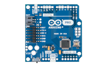
- Arduino Pro Mini: This board has the same processor but it has much smaller form factor. You can do your prototypes using Arduino Uno Rev3 and use Pro Mini for your final build as it takes much less space.
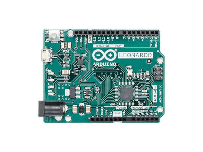
- Arduino Leonardo: The Leonard board has the same form factor of the Arduino Uno Rev3 but it uses ATmega32U4. That processor has USB to serial converter, so it doesn't need to have a dedicated chip for that. Also it is an SMD component which takes less space on the board.
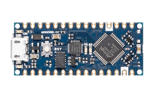
- Arduino Nano: The Nano board utilizes the ATmega328 and is breadboard friendly. This makes is much easier to use for prototyping and for beginners.
Arduino Uno Rev3 Projects
Here you can find a list of top 5 projects using Arduino Uno Rev3 that would hopefully sparkle an idea on your mind for your next project:
- A Plant Watering System Powered by Arduino Uno Rev3
- Super Simple Beginner's Robot
- Arduino CNC
- Arduino Uno Water Heater Thermostat for PWM Pumps
- Arduino UNO Guitar Pedal
Platform
| Manufacturer | Arduino |
| Processor | ATmega328 |
| Processor Family | AVR |
| Clock Speed | 16 Mhz |
| Flash Memory | 32 KB |
| SRAM | 2 KB |
| EEPROM | 1 KB |
| Programming |
I/O
| Digital I/O | 14 |
| Analog Input | 6 |
| PWM | 6 |
| ADC Resolution | 1024 |
| Interrupts | 2 |
Power
| Input Voltage | 7-12 V |
| I/O Voltage | 5 V |
| I/O Current | 20 mA |
Communication Protocols
| I2C | 1x |
| SPI | 1x |
| USART | 1x |
Connectivity
| USB Type B | 1x |
Peripherals
| Timer | 2x 8 bit 1x 16 bit |
Dimensions
| Width | 53.4 mm |
| Length | 68.6 mm |
| Weight | 25 g |